
Medium-frequency induction carburizing furnace

A carburizing furnace, intermediate frequency technology, applied in the field of intermediate frequency induction carburizing furnace, can solve the problems of affecting output, difficult operation, mutual contact, etc., to ensure carburizing stability, high-efficiency carburizing effect, and improving practicability.

Pending Publication Date: 2022-07-29
马雅盛
View PDF0 Cites 0 Cited by
  • Summary
  • Abstract
  • Description
  • Claims
  • Application Information

AI Technical Summary

Problems solved by technology

[0004] At this stage, there are some new carburizing furnace equipment on the market, which adopt the method of ventilating mesh cylinder for carburizing work, and the carburizing gas discharged from the methane gas outlet rod penetrates the connection port of the ventilating mesh cylinder to carburize the workpiece. Although most components can be well carburized, when carburizing small-diameter spherical workpieces, such as bearing balls and other workpieces, due to the rolling properties of spherical workpieces, when a large number of spherical workpieces are placed in the furnace When the workpiece is removed, it will cause mutual contact between spherical workpieces, which will affect the efficient carburizing effect on the surface of spherical workpieces. When a small amount of spherical workpieces are placed in the furnace, the output will be affected, thereby affecting the carburization stability of spherical workpieces. , and it is difficult to operate when adding or removing

Method used

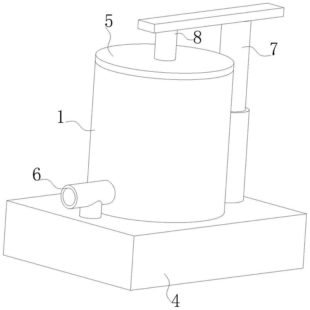
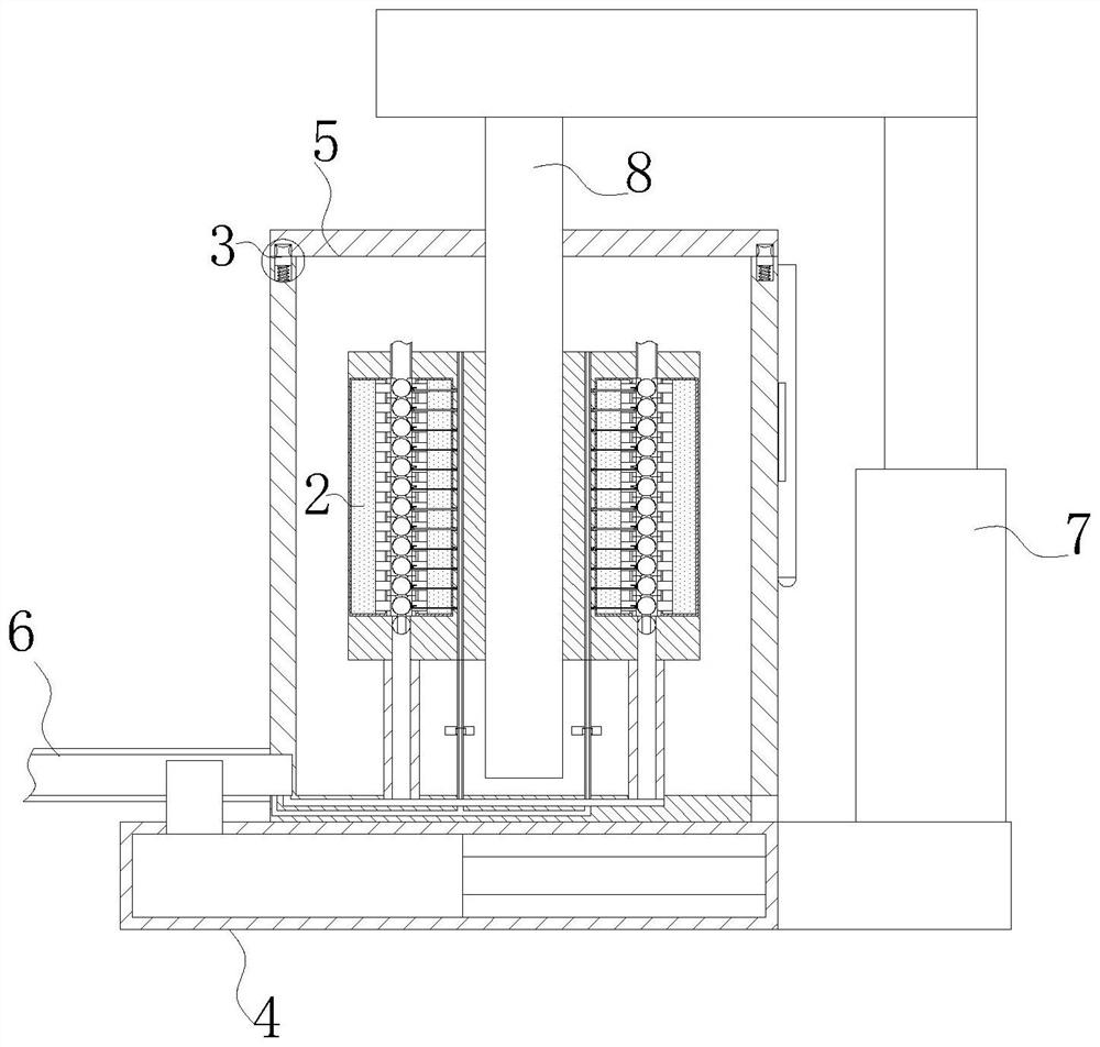
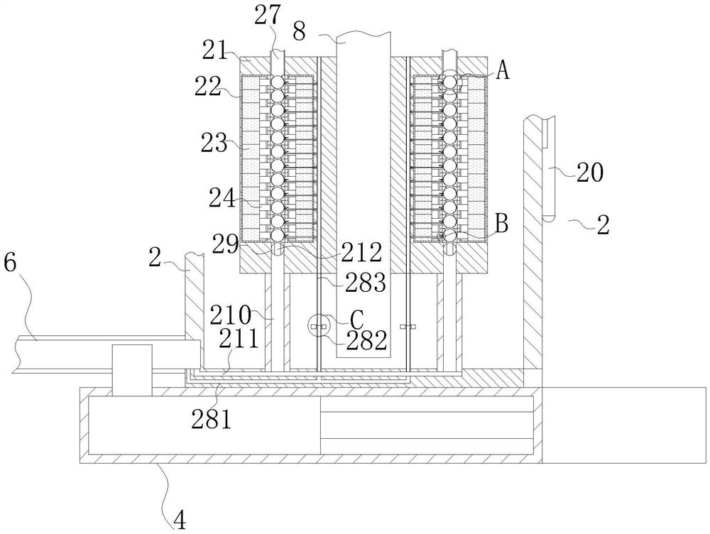

Image

  • Medium-frequency induction carburizing furnace
  • Medium-frequency induction carburizing furnace
  • Medium-frequency induction carburizing furnace

Examples


Embodiment Construction

[0037] The technical solutions in the embodiments of the present invention will be clearly and completely described below with reference to the accompanying drawings in the embodiments of the present invention. Obviously, the described embodiments are only a part of the embodiments of the present invention, rather than all the embodiments. Based on the embodiments of the present invention, all other embodiments obtained by those of ordinary skill in the art without creative efforts shall fall within the protection scope of the present invention.

[0038] In the description of the present invention, it should be understood that the terms "center", "longitudinal", "lateral", "length", "width", "thickness", "upper", "lower", "front", " Or The positional relationship is based on the orientation or positional relationship shown in the accompanying drawings, which is only for the convenience of describing the present invention and simplifying the description, rather than indicating ...


PUM


Abstract

The invention relates to the technical field of carburizing furnaces, in particular to a medium-frequency induction carburizing furnace which comprises a carburizing furnace body. The medium-frequency induction part is arranged on the outer surface of the lower end of the carburizing furnace body; the gas inlet pipe is connected to the position, close to the upper end of the medium-frequency induction piece, of the outer surface of one side of the carburizing furnace body in a penetrating mode, and the gas inlet pipe is connected with the middle of the medium-frequency induction piece through a pipeline in a penetrating mode; and a telescopic member. By arranging the auxiliary mechanism, after spherical workpieces are mounted, the spherical workpieces can be uniformly separated, so that the spherical workpieces cannot be in contact with one another, and when the spherical workpieces are carburized, the phenomenon that the spherical workpieces have certain rolling property, and when a large number of spherical workpieces are placed in the furnace body, the spherical workpieces are not prone to being damaged is avoided. The problem that the spherical workpieces make contact with one another due to the fact that the spherical workpieces are heated, the efficient carburizing effect on the surfaces of the spherical workpieces is guaranteed, the carburizing stability of the spherical workpieces is guaranteed, adding or taking-out operation is easy, and the overall practicability is improved.

Description

technical field [0001] The invention relates to the technical field of carburizing furnaces, in particular to an intermediate frequency induction carburizing furnace. Background technique [0002] Carburizing refers to the process of infiltrating carbon atoms into the surface layer of steel, and it is also the process of making the steel parts of low carbon steel have the surface layer of high carbon steel, and then quenching and tempering at low temperature, so that the surface layer of the steel parts has high hardness and wear resistance. Therefore, in order to maintain the toughness and plasticity of low carbon steel, it is necessary to carburize the steel parts. [0003] In the medium frequency induction carburizing furnace, the workpiece is carburized by the principle of medium frequency induction. Intermediate frequency induction heating means that when the magnetic flux surrounded by the conductor loop changes, an induced potential will be generated in the loop. Sim...

Claims


Application Information

Patent Timeline
IPC IPC(8): C23C8/22F27D5/00
CPCC23C8/22F27D5/00F27D2005/0081
Inventor 马雅盛王涛李文乾
Owner 马雅盛
Learn More