
Waterproof strip welding equipment capable of preventing protruding burrs

A technology for welding equipment and waterproof strips, applied in shearing machine equipment, metal processing equipment, other manufacturing equipment/tools, etc., can solve the problem of local bulge at the welding place, uneven ends of waterproof strips, and inability to ensure that two waterproof strips are exposed. Part of the same problem

Pending Publication Date: 2022-07-29
陈滴生
View PDF10 Cites 0 Cited by
  • Summary
  • Abstract
  • Description
  • Claims
  • Application Information

AI Technical Summary

Problems solved by technology

[0003] In order to overcome the deflection that occurs when the waterproof strip is cut manually with a knife, the end of the waterproof strip is uneven, and the manual pushing of the waterproof strip cannot ensure that the exposed parts of the two waterproof strips are the same, both of which will cause local bulges at the welded part after welding The shortcoming of the present invention provides a kind of waterproof strip welding equipment that prevents raised burrs

Method used


Image

  • Waterproof strip welding equipment capable of preventing protruding burrs
  • Waterproof strip welding equipment capable of preventing protruding burrs
  • Waterproof strip welding equipment capable of preventing protruding burrs

Examples


Embodiment 1

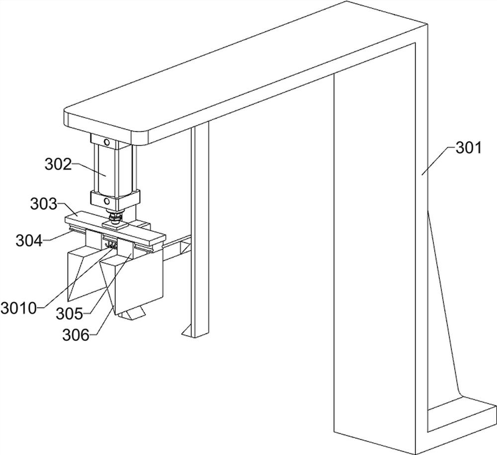
[0036] A waterproof strip welding equipment for preventing raised burrs, such as Figure 1-14 As shown, it includes a foot 1, a first mounting plate 2, a welding unit, a cutting unit and a heating and softening unit; the top of the four feet 1 is fixedly connected with a first mounting plate 2; the upper front of the first mounting plate 2 A welding unit is connected; a cutting unit is connected to the upper rear of the first mounting plate 2 ; a heating and softening unit is connected to the upper side of the first mounting plate 2 ; the cutting unit is connected to the heating and softening unit.

[0037] The welding unit includes a first mounting frame 201, a motor 202, a second mounting plate 203, a first double helix screw 204, a third polished rod 205, a welding assembly 206 and a first gear 207; the upper front part of the first mounting plate 2 Two second mounting plates 203 are fixedly connected to the upper side of the first mounting frame 201 by bolts, and the two s...

Embodiment 2

[0045] On the basis of Example 1, as figure 1 and Figure 15-18 As shown, it also includes a tensile detection unit; the upper side of the first mounting plate 2 is connected with a tensile detection unit; The first electric push rod 504, the rod sleeve 505, the twelfth installation plate 506, the third gear 507, the thirteenth installation plate 508, the first spring telescopic rod 509, the first block 5010, the second block 5011, the first Three wedge block 5012, fourth wedge block 5013, first transmission wheel 5014, fifth mounting frame 5015, third double helix screw 5016, second polished rod 5017, second transmission wheel 5018, fifteenth mounting plate 5019, Two spring telescopic rods 5020, a third clamping block 5021, a sixth wedge block 5022 and a fifth wedge block 5023; the upper side of the first mounting plate 2 is bolted with a fourth mounting frame 501 and a fifth mounting frame 5015, and the fifth mounting The frame 5015 is located at the rear of the fourth mount...


PUM


Abstract

The invention relates to the field of waterproof strips, in particular to waterproof strip welding equipment capable of preventing protruding burrs. The technical problems that when a waterproof strip is cut manually through a cutter, deviation can happen, the end of the waterproof strip is uneven, it cannot be guaranteed that the exposed parts of the two waterproof strips are the same when the waterproof strip is manually pushed, and the two waterproof strips can locally protrude after welding are solved. According to the technical scheme, the waterproof strip welding equipment capable of preventing the protruding burrs comprises a first mounting plate, a welding unit and the like; the front portion of the upper side of the first mounting plate is connected with a welding unit. Welding of the waterproof strips is achieved, the ends of the waterproof strips are flattened through longitudinal cutting of the cutter, meanwhile, the exposed parts of the two waterproof strips are the same through the limiting effect of the cutter, the phenomenon that after welding, the welding position locally protrudes is avoided, in addition, a heating softening tool is cleaned in real time, and the working efficiency is improved. And the phenomenon that subsequent softening of the waterproof strips is seriously affected due to accumulation of the adhered waterproof strips is avoided.

Description

technical field [0001] The invention relates to the field of waterproof strips, in particular to a welding device for waterproof strips that prevents raised burrs. Background technique [0002] At present, when welding waterproof strips for windows, the two waterproof strips are first clamped and fixed with a mold, and then the ends of the waterproof strips are manually cut to be flat, and then the waterproof strips are manually pushed to expose a part of the strips, and the exposed parts are exposed. Heating and softening, welding after softening, however, when manually cutting the waterproof strip with a tool, the offset will occur, resulting in uneven ends of the waterproof strip, and manual pushing of the waterproof strip cannot ensure that the exposed parts of the two waterproof strips are the same, both of which will lead to After welding, the welding part is partially raised, which affects the use of the waterproof strip. In addition, the surface of the heating and so...

Claims


Application Information

Patent Timeline
Patent Type & Authority Applications(China)
IPC IPC(8): B23P23/04B23D15/00B23D33/00B26D1/06B26D7/00
CPCB23P23/04B23D15/00B23D33/00B26D1/06B26D7/00
Inventor 陈滴生
Owner 陈滴生
Learn More