
RIS and beam forming method and device based on RIS

A beamforming method and base station technology, applied in diversity/multi-antenna systems, space transmit diversity, electrical components, etc., can solve the problems of RIS unit estimation, reduce the amount of beamforming calculations, and consume huge pilot overhead, etc. Achieve the effect of reducing pilot overhead

Pending Publication Date: 2022-07-22
TSINGHUA UNIV
View PDF0 Cites 0 Cited by
  • Summary
  • Abstract
  • Description
  • Claims
  • Application Information

AI Technical Summary

Problems solved by technology

[0005] The purpose of the present invention is to provide a RIS and RIS-based beamforming method and device to overcome the problem that the RIS unit cannot provide effective information for channel estimation and thus requires a huge pilot overhead to achieve beamforming, so as to reduce the Pilot overhead and reduce beamforming computation

Method used


Image

  • RIS and beam forming method and device based on RIS
  • RIS and beam forming method and device based on RIS
  • RIS and beam forming method and device based on RIS

Examples


Embodiment Construction

[0054] Combine below Figure 2-Figure 6 Describe a RIS and RIS-based beamforming method and apparatus provided by the present invention.

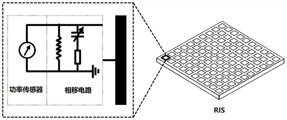
[0055] First, as figure 2 As shown, the present invention provides a RIS, the RIS is composed of a plurality of RIS units arranged in an array;

[0056] The RIS unit includes: a phase shift circuit and a power sensor connected in parallel with the phase shift circuit;

[0057] Wherein, the phase shift circuit is used to regulate the phase of the incident signal of the corresponding RIS unit;

[0058] The power sensor is used to sense the power of the electromagnetic field at the location where the corresponding RIS unit is located.

[0059] It should be noted that the purpose of the power sensor is to obtain the power of the radio frequency signal at its location, and its implementation includes but is not limited to a power sensor, that is, any hardware that can produce an equivalent effect can replace the power sensor of this applicat...


PUM


Abstract

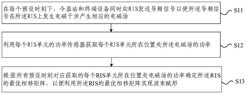
The invention relates to an RIS and a beam forming method and device based on the RIS, and each unit RIS is connected in parallel with a power sensor at the two ends of a phase shift circuit, so as to obtain the signal power at the position. The beam forming method based on the RIS comprises the following steps: at each preset moment, enabling a base station and terminal equipment to send pilot signals to the RIS at the same time, so that the pilot signals generate electromagnetic interference on the RIS to generate a corresponding electromagnetic field; acquiring the power of the electromagnetic field at the position of each RIS unit by using the power sensor of each RIS unit; and determining an optimal phase shift matrix of the RIS according to the power of the electromagnetic field at the position where each RIS unit is located, which is correspondingly acquired at all preset moments, so as to realize beam forming by using the optimal phase shift matrix of the RIS. According to the invention, a brand new beam forming method is designed, so that the channel estimation pilot frequency overhead required by beam forming is irrelevant to the number of RIS units, and the pilot frequency overhead required by beam forming is greatly reduced.

Description

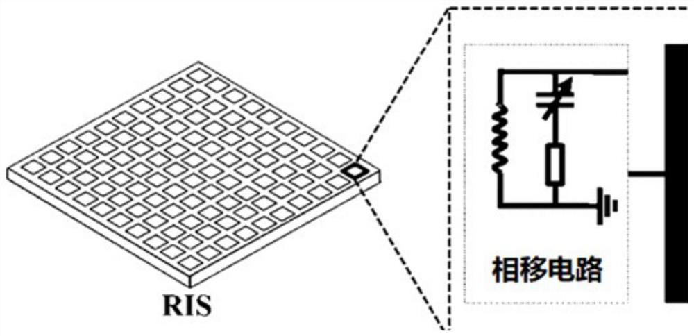
technical field [0001] The present invention relates to the technical field of wireless mobile communications, and in particular, to a RIS and a RIS-based beamforming method and device. Background technique [0002] RIS (Reconfigurable Intelligent Surface) is a large-scale array composed of a large number of passive units (RIS units) that can control the phase of the signal. direction, its specific structure is as figure 1 shown. Because the cost and power consumption of RIS are very low, it has application value in scenarios such as overcoming interruptions, increasing capacity, and saving power generation. Therefore, RIS technology is considered to be a promising technology in future 6G communications. [0003] In order to maximize the signal-to-noise ratio when using RIS-assisted multi-antenna system communication, each RIS unit needs to adjust the appropriate phase shift to achieve optimal beamforming. In the current RIS-based beamforming method, CSI (Channel State In...

Claims


Application Information

Patent Timeline
IPC IPC(8): H04B7/06H04B7/08H04B7/0456
CPCH04B7/0617H04B7/0626H04B7/086H04B7/0857H04B7/0456
Inventor 戴凌龙朱结奥刘坤瓒李智毅万钟志超
Owner TSINGHUA UNIV
Learn More