
Square wave chamfering circuit and display panel

A technology of cutting corners and circuits, which is applied in the direction of electrical components, static indicators, output power conversion devices, etc., can solve the problem of large voltage drop of panel driving voltage, and achieve the effect of solving large voltage drop

Active Publication Date: 2022-07-22
SHENZHEN CHINA STAR OPTOELECTRONICS SEMICON DISPLAY TECH CO LTD
View PDF3 Cites 0 Cited by
  • Summary
  • Abstract
  • Description
  • Claims
  • Application Information

AI Technical Summary

Problems solved by technology

[0003] The application provides a square-wave angle-cutting circuit and a display panel to solve the problem of large voltage drop of the display panel driving voltage

Method used


Image

  • Square wave chamfering circuit and display panel
  • Square wave chamfering circuit and display panel
  • Square wave chamfering circuit and display panel

Examples


Embodiment Construction

[0032] The technical solutions in the embodiments of the present application will be clearly and completely described below with reference to the drawings in the embodiments of the present application. Obviously, the described embodiments are only a part of the embodiments of the present application, rather than all the embodiments. Based on the embodiments in this application, all other embodiments obtained by those skilled in the art without creative efforts shall fall within the protection scope of this application.

[0033] In the description of this application, it should be understood that the terms "first" and "second" are only used for description purposes, and cannot be interpreted as indicating or implying relative importance or implicitly indicating the number of indicated technical features. Thus, features defined as "first", "second" may expressly or implicitly include one or more of said features. In the description of the present application, "plurality" means t...


PUM


Abstract

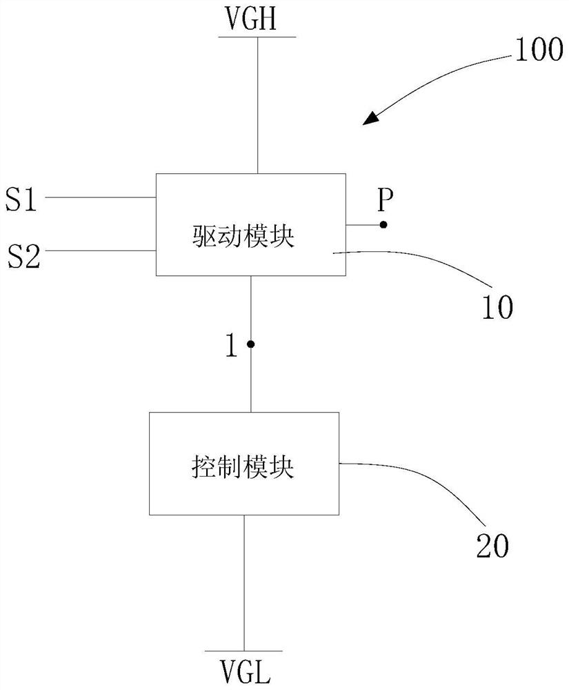
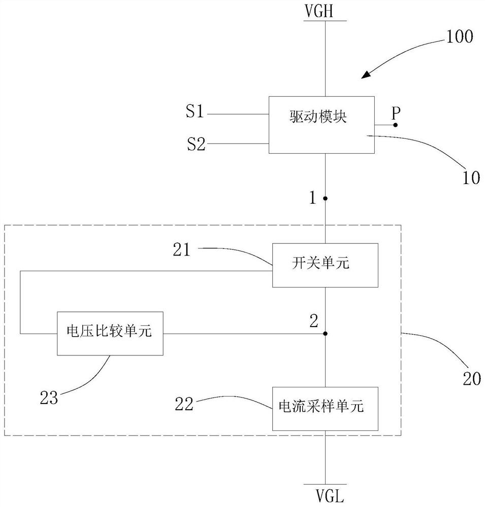
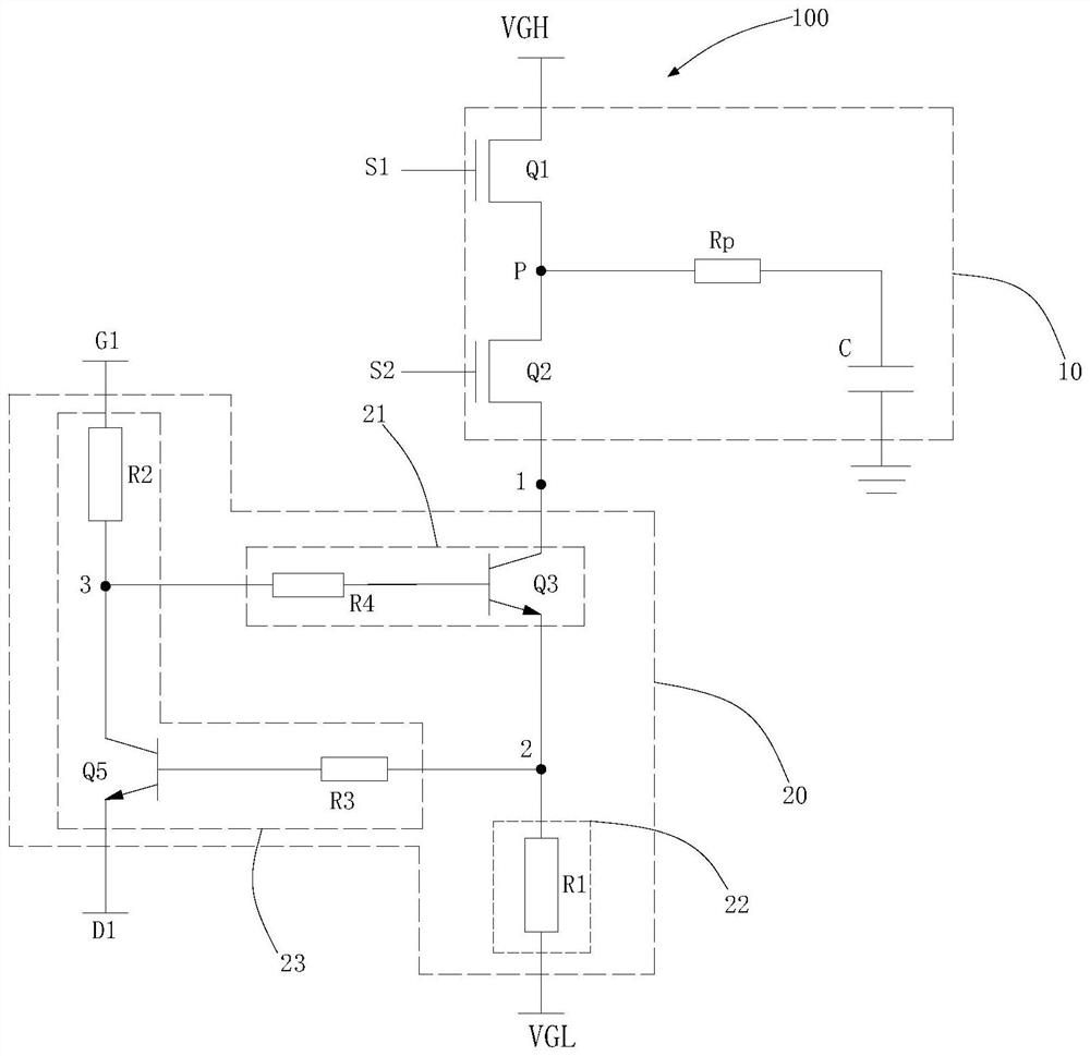
The invention discloses a square wave angle cutting circuit and a display panel. The square wave angle cutting circuit comprises a first power supply signal access end; a second power supply signal access end; the driving module is respectively connected with the first power supply signal access end, the first node, the output node, the first control signal access end and the second control signal access end; the control module is respectively connected with the first node and the second power supply signal access end; wherein the control module is used for controlling the output node to output a chamfering signal based on the current between the control module and the second power supply signal access end. According to the invention, the control module controls the output node to output the chamfering signal based on the current between the control module and the second power signal access end, so that the voltage output by the output node has a slowly-decreasing gradient, and the problem that the voltage drop value of the driving voltage of the display panel is large is solved.

Description

technical field [0001] The present application relates to the field of display technology, and in particular, to a square wave clipping circuit and a display panel. Background technique [0002] With the development of display technology, the display panel adopts the gate driving circuit to complete the function of progressive scanning, which reduces the production cost of the display panel and also meets the requirements of the narrow frame of the display panel. However, the square wave drive signal output by the gate drive circuit has a process of high and low level switching. When the gate scan signal changes from high level to low level, the square wave drive signal output by the gate drive circuit will also change from high level to high level. The drive voltage of the display panel also drops sharply from a high level to a low level instantaneously. Bad phenomena such as flicker and afterimage seriously affect the quality of the picture displayed on the display panel....

Claims


Application Information

Patent Timeline
Patent Type & Authority Applications(China)
IPC IPC(8): H03K5/08H02M1/088G09G3/20
CPCH03K5/08H02M1/088G09G3/20Y02B70/10G09G3/2092G09G3/3677G09G2300/0842G09G2310/0267G09G2310/0294G09G2310/08
Inventor 高选全
Owner SHENZHEN CHINA STAR OPTOELECTRONICS SEMICON DISPLAY TECH CO LTD
Learn More