Eureka AIR delivers breakthrough ideas for toughest innovation challenges, trusted by R&D personnel around the world.

Bus duct with fireproof function

A technology of busway and function, which is applied in the direction of fully enclosed busbar devices, fire rescue, etc., can solve the problems of burning damage, fire, loss and other problems of parts, and achieve the effect of reducing negative impact, ensuring safety and preventing continuous burning

Inactive Publication Date: 2022-07-22
陆柳蕙
View PDF0 Cites 2 Cited by
  • Summary
  • Abstract
  • Description
  • Claims
  • Application Information

AI Technical Summary

Problems solved by technology

[0003] In Guangzhou, Guangdong, my country, where the power distribution room of a building with more than 12 floors goes out, more than 90% of the main lines leading to the floor use bus ducts; 630KVA transformers to power distribution cabinets use bus ducts. There will be a risk of fire caused by high pressure and high temperature, and the existing busway with fireproof function has the following problems: 1. It has been used for a long time or exposed to high temperature, humidity or corrosive environment for a long time, and the insulation layer is aging, which makes the busway The trough itself is prone to fire, and the fire source cannot be effectively eliminated when the fire occurs, causing the burning of the busway to cause great danger to the work of the high-voltage lines in the distribution box; The parts are burned and damaged. If the burning position cannot be effectively covered and the high temperature inside the busway can be effectively prevented, the busway will catch fire, causing the safety of the entire circuit and causing huge losses.

Method used


Image

  • Bus duct with fireproof function
  • Bus duct with fireproof function
  • Bus duct with fireproof function

Examples


Embodiment Construction

[0033] The present invention will be described in detail below, and the technical solutions in the embodiments of the present invention will be described clearly and completely. Obviously, the described embodiments are only a part of the embodiments of the present invention, rather than all the embodiments. Based on the embodiments of the present invention, all other embodiments obtained by those of ordinary skill in the art without creative efforts shall fall within the protection scope of the present invention.

[0034] The present invention provides a kind of busway with fireproof function through improvement, and the technical scheme of the present invention is:

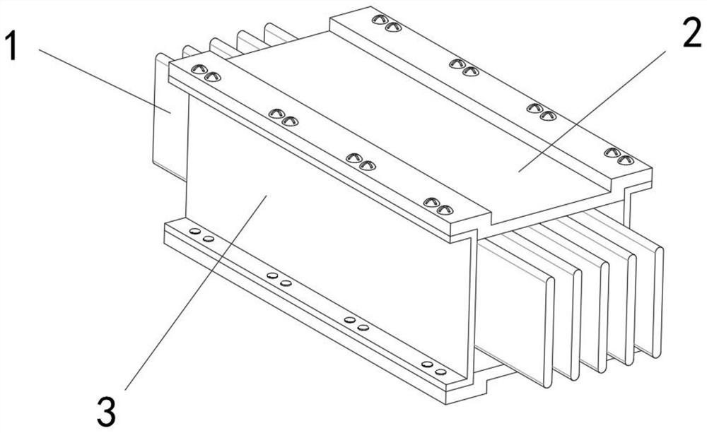
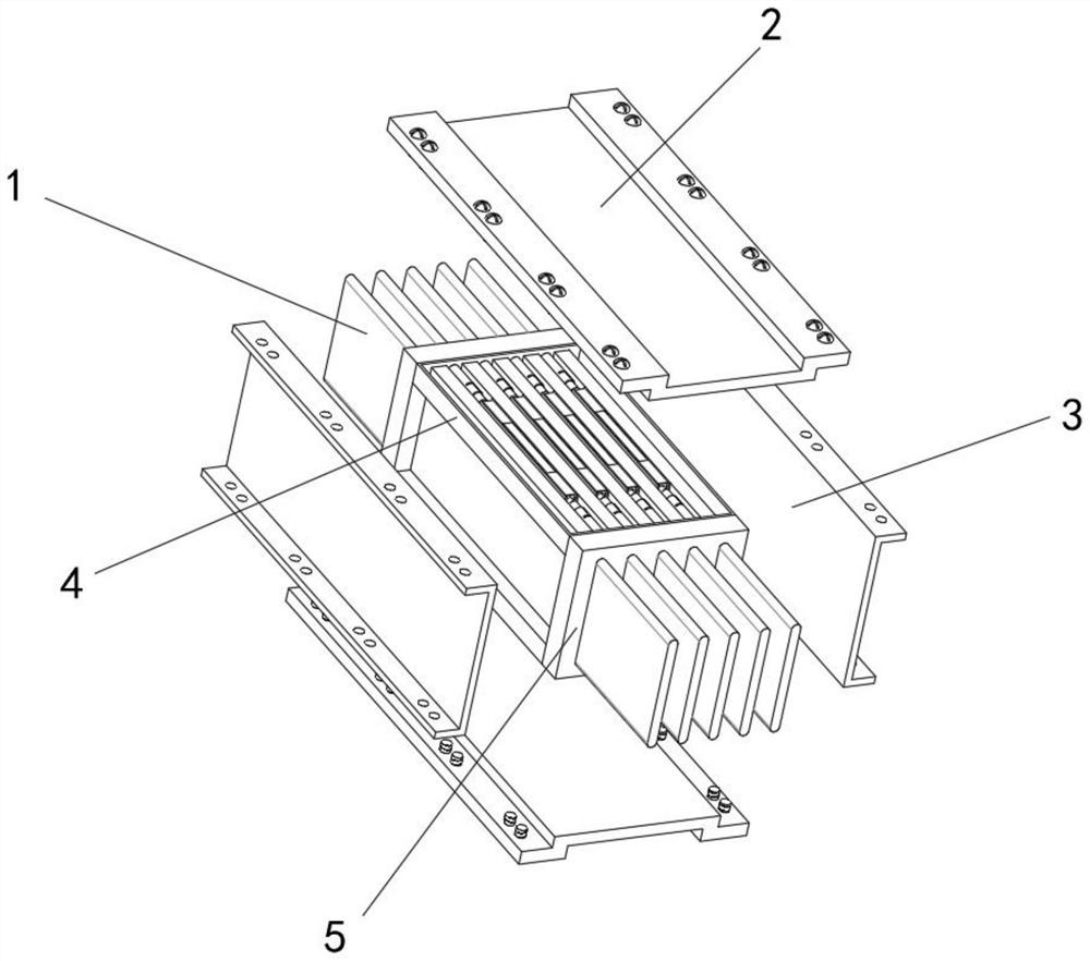
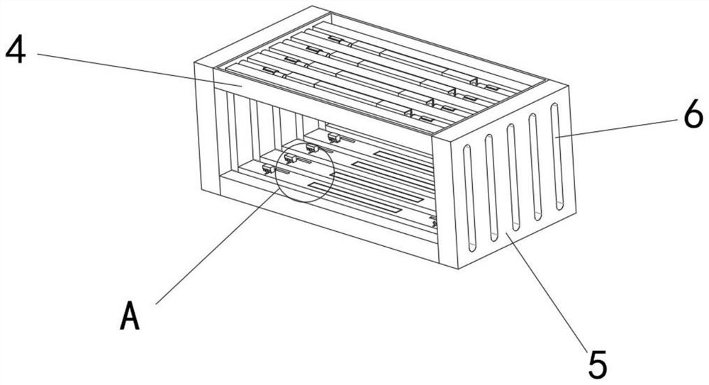
[0035] refer to figure 1 , figure 2 and image 3 , a bus duct with fireproof function, including side plate 3, two top plates 2 are connected by screws on the outer walls on both sides of the side plate 3, and two flame-retardant partitions 5 are connected between the top plate 2 and the side plate 3 by screws...


PUM


Abstract

The invention particularly relates to a bus duct with a fireproof function, which comprises a side plate, two top plates are connected to the outer walls of the two sides of the side plate through screws, two flame-retardant partition plates are connected to the top plates and the side plate through screws, and a plurality of through grooves which are linearly and uniformly distributed are formed in the flame-retardant partition plates. According to the invention, when combustion occurs in the bus duct, high temperature enables the corresponding paraffin fixing blocks to be quickly melted, so that contact pressure cannot be applied to the clamping strips, and the clamping strips cannot be damaged, so that the service life of the bus duct is prolonged, and the service life of the bus duct is prolonged. The flame retardant storage boxes rapidly release the flame retardant through internal action, the flame retardant is exploded out through the plastic film, an ignition point is rapidly covered for extinguishment, continuous combustion at a fire source is effectively prevented, meanwhile, when a large-range fire breaks out on the bus duct, the multiple internal flame retardant storage boxes simultaneously release the flame retardant for flame retardance, internal gaps of the bus duct are filled with the flame retardant, and the flame retardant effect is good. And the circuit safety of bus duct connection is ensured.

Description

technical field [0001] The invention relates to the technical field of bus ducts, in particular to a bus duct with fireproof function. Background technique [0002] The busway is a closed metal device composed of copper and aluminum busbars, which is used to distribute large power to each element of the dispersion system. Electric wires and cables have been increasingly replaced in indoor low-voltage power transmission trunk projects. [0003] In Guangzhou, Guangdong, my country, where the power distribution room of buildings above 12 floors goes out, that is, more than 90% of the main lines leading to the floors use bus ducts; 630KVA transformers should use bus ducts to power distribution cabinets. During this high-voltage transmission process, the bus ducts There is a danger of causing fire due to high pressure and high temperature, and the existing bus ducts with fire protection function have the following problems: 1. After being used for a long time or exposed to high t...

Claims


Application Information

Patent Timeline
Patent Type & Authority Applications(China)
IPC IPC(8): H02G5/06A62C3/16
CPCH02G5/06A62C3/16
Inventor 陆柳蕙
Owner 陆柳蕙
Why Eureka
Eureka Blog
Learn More