Eureka AIR delivers breakthrough ideas for toughest innovation challenges, trusted by R&D personnel around the world.

Pacemaker sandbag fixer

A pacemaker and fixator technology, used in medical science, surgery, etc., can solve the problems of inconvenient sandbag fixation of different sizes, ventilation, poor dehumidification, and poor practicability, and achieves improved practicability. Effect

Pending Publication Date: 2022-07-22
颍上县人民医院
View PDF0 Cites 0 Cited by
  • Summary
  • Abstract
  • Description
  • Claims
  • Application Information

AI Technical Summary

Problems solved by technology

[0003] Pacemaker sandbag holders in the prior art are mostly inconvenient to fix sandbags of different sizes, have poor practicability, cannot make the sandbags well fixed on the patient's body, and have poor air permeability and dehumidification. For this reason, We propose pacemaker sandbag holder

Method used


Image

  • Pacemaker sandbag fixer
  • Pacemaker sandbag fixer
  • Pacemaker sandbag fixer

Examples


Embodiment 1

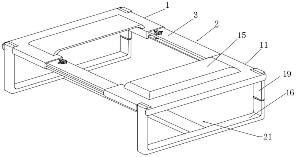
[0027] The embodiment of the present invention discloses a pacemaker sandbag holder. refer to Figure 1-7 , a pacemaker sandbag holder, including a fixing frame 1 and a fixing frame 2 11, an adjustment mechanism 2 is arranged between the fixing frame 1 and the fixing frame 2 11, and the upper ends of the fixing frame 1 and the fixing frame 2 11 are close to the edge of the inner side wall A limiting net 15 is set at the position, and movable grooves 14 are provided at the corners of the fixing frame 1 and the fixing frame 2 11. The inside of the movable groove 14 is respectively provided with a strap 1 16 and a strap 2 19, one of the two sets of strap 1 16. A protective mechanism 21 is provided between.

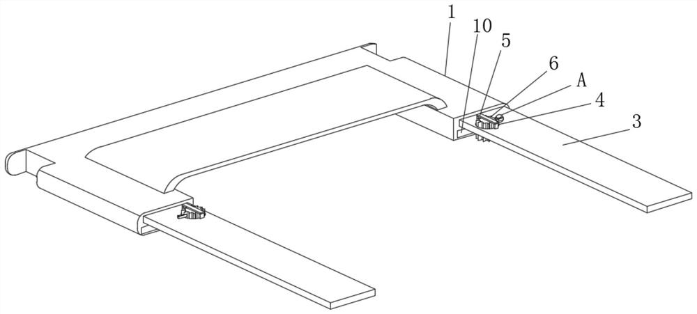
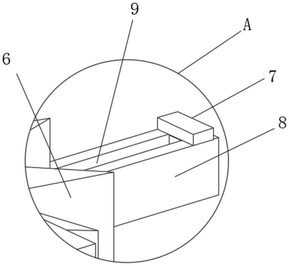
[0028] refer to Figure 2-4 , the adjustment mechanism 2 includes an adjustment plate 1 3, the upper end of the adjustment plate 1 3 is provided with a groove 4 at a position close to the fixing frame 1, the upper end of the adjustment plate 1 3 and close to the edge of the...

Embodiment 2

[0033] The embodiment of the present invention discloses a pacemaker sandbag holder. refer to Figure 1-7 , pacemaker sandbag holder, including fixing frame 1 1 and fixing frame 2 11, an adjustment mechanism 2 is arranged between fixing frame 1 1 and fixing frame 2 11, the upper end of fixing frame 1 and fixing frame 2 11 is close to the edge of the inner side wall A limiting net 15 is provided at the position, and movable grooves 14 are provided at the corners of the fixing frame 1 and the fixing frame 2 11. The interior of the movable groove 14 are respectively provided with a strap 1 16 and a strap 2 19, one of the two sets of strap 1 16. A protective mechanism 21 is provided between.

[0034] refer to Figure 6-7 , the protection mechanism 21 includes a backing plate 22, a dehumidification groove 23 is provided on one side of the backing plate 22, a sliding groove 25 is provided on both inner side walls of the dehumidification groove 23, and a placement groove 24 is prov...


PUM


Abstract

The pacemaker sandbag fixator comprises a first fixing frame and a second fixing frame, an adjusting mechanism is arranged between the first fixing frame and the second fixing frame, limiting nets are arranged at the positions, close to the edges of the inner side walls, of the upper ends of the first fixing frame and the second fixing frame, and movable grooves are formed in the corner positions of the first fixing frame and the second fixing frame. First bandages and second bandages are arranged in the movable grooves correspondingly, a protection mechanism is arranged between the two first bandages, the adjusting mechanism comprises a first adjusting plate, and a groove is formed in the position, close to the first fixing frame, of the upper end of the first adjusting plate; according to the fixing device, sandbags of different sizes can be conveniently clamped and limited, so that the fixing device is suitable for the sandbags of different sizes, the practicability of the fixing device is effectively improved, the sandbags can be well fixed to the body of a patient, meanwhile, sweat generated at the contact position of the back of the patient and the base plate can be absorbed, the sandbags are kept dry, and the comfort is improved.

Description

technical field [0001] The invention relates to the field of pacemakers, in particular to a pacemaker sandbag holder. Background technique [0002] The pacemaker refers to the entire pacing system, which consists of a pacemaker, pacing lead wires and a program controller. The pacemaker and the pacing electrode lead are implanted in the human body. A pacemaker consists of a circuit and a battery installed in a metal box. The pacemaker sends tiny electrical pulses to the heart when needed. The pacing lead is made up of insulated wires, which are responsible for sending tiny electrical pulses to the heart and stimulating the heart to beat. ; [0003] Most of the pacemaker sandbag fixers in the prior art are inconvenient to fix sandbags of different sizes, have poor practicability, cannot fix the sandbags well on the patient's body, and have poor ventilation and dehumidification. We propose pacemaker sandbag holders. SUMMARY OF THE INVENTION [0004] In order to solve the ...

Claims


Application Information

Patent Timeline
IPC IPC(8): A61B17/12
CPCA61B17/12
Inventor 张晶王苗王瑞
Owner 颍上县人民医院
Why Eureka
Eureka Blog
Learn More