
Turbine blade disassembly tool and method

A technology for removing turbine blades and dismantling tools, which is applied in manufacturing tools, metal processing, metal processing equipment, etc. It can solve the problems of impossibility of dismantling turbine blades and difficulty in assembly, and achieve the effect of reducing operation difficulty and improving efficiency

Active Publication Date: 2022-07-19
AECC COMML AIRCRAFT ENGINE CO LTD
View PDF12 Cites 0 Cited by
  • Summary
  • Abstract
  • Description
  • Claims
  • Application Information

AI Technical Summary

Problems solved by technology

However, the matching structure of the oblique tenon groove and the oblique turbine blade brings difficulty in assembly
When the turbine blades need to be removed from the turbine disk, the adjacent turbine blades restrict each other, making it impossible to simply remove the turbine blades from the turbine disk

Method used


Image

  • Turbine blade disassembly tool and method
  • Turbine blade disassembly tool and method
  • Turbine blade disassembly tool and method

Examples


Embodiment Construction

[0040] Various exemplary embodiments of the present disclosure will now be described in detail with reference to the accompanying drawings. The description of the exemplary embodiments is merely illustrative and in no way limits the disclosure, its application or uses in any way. The present disclosure may be implemented in many different forms and is not limited to the embodiments described herein. These embodiments are provided so that this disclosure will be thorough and complete, and will fully convey the scope of the disclosure to those skilled in the art. It should be noted that unless specifically stated otherwise, the relative arrangements of parts and steps, compositions of materials, numerical expressions and numerical values ​​set forth in these embodiments are to be interpreted as illustrative only and not as limiting.

[0041] As used in this disclosure, "first," "second," and similar words do not denote any order, quantity, or importance, but are merely used to ...


PUM


Abstract

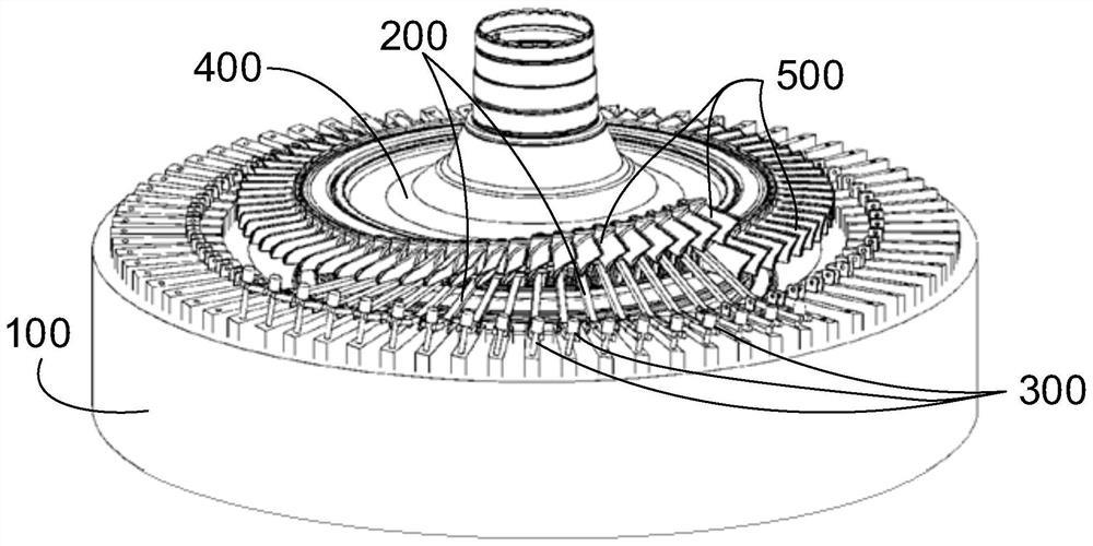
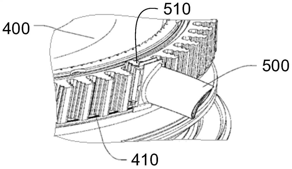
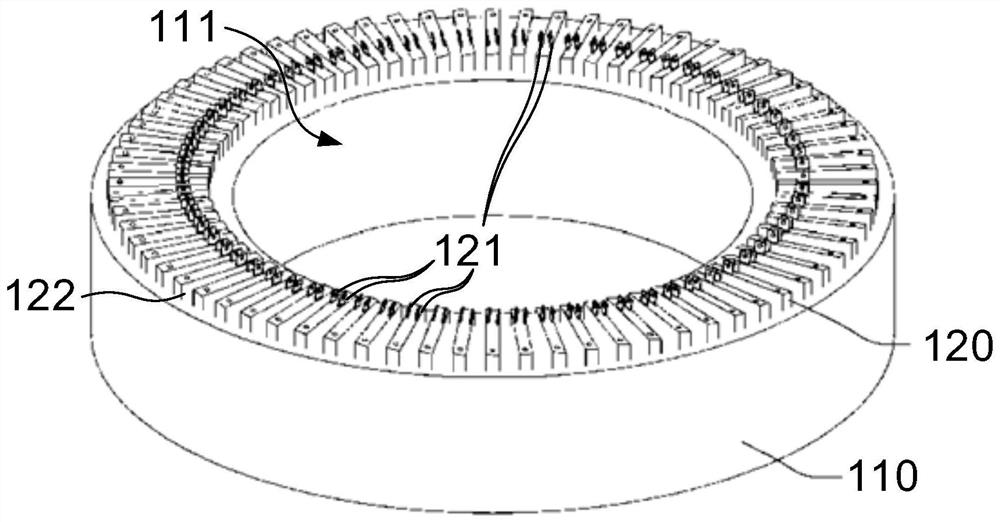
The present disclosure relates to a turbine blade removal tool and method for removing a plurality of turbine blades (500) mounted on a turbine disk (400). The turbine blade removal tool comprises: a support (100); the multiple supporting arms (200) are pivoted to the support (100) through pivots (240) respectively, and each supporting arm (200) is provided with an abutting end (211) used for supporting at least one turbine blade (500) installed on the turbine disc (400) and an operation end (221) far away from the abutting end (211) relative to the pivots (240); and the multiple connecting pieces (300) are configured to be connected between the operation ends (221) of the supporting arms (200) and the support (100) so as to maintain the state that the abutting ends (211) of the supporting arms (200) support the turbine blades (500). According to the embodiment of the invention, the dismounting difficulty can be reduced.

Description

technical field [0001] The present disclosure relates to the field of aero-engine assembly, and in particular, to a turbine blade disassembly tool and method. Background technique [0002] Among the many components of aero-engines, the turbine blades are subjected to very severe forces due to their high temperature and high rotational speed, and the force between them and the turbine disk is also very large. In order to optimize the force between the turbine blade and the turbine disk, the tenon of the turbine blade and the tenon of the turbine disk are usually designed to be inclined at an angle to the engine axis to increase the contact area between the two. However, the matching structure of the inclined tongue and groove and the inclined turbine blade brings about the difficulty of assembly. When the turbine blades need to be removed from the turbine disk, the adjacent turbine blades restrict each other, so that the turbine blades cannot be simply removed from the turbi...

Claims


Application Information

Patent Timeline
Patent Type & Authority Applications(China)
IPC IPC(8): B23P19/02
CPCB23P19/02Y02E10/20
Inventor 季寅泽刘震宇范骏鹏
Owner AECC COMML AIRCRAFT ENGINE CO LTD
Learn More