


Quick Research
Generate reliable direction feasibility study reports for your R&D in just a few steps.

Technical Q&A
Discover and master advanced knowledge NOW. Basics, ideas, possibilities, all at once.

Find Solutions
As an expert in R&D theories, this can generate solutions to your technical problems instantly.

Evaluate Feasibility
Analyze your overall solution with one click, know your potential R&D risks in advance.

Monitor Landscape
Get weekly tech updates, stay abreast of the latest tech innovations and key insights.
Piezoelectric type electrostatic chuck
An electrostatic chuck and piezoelectric technology, which is applied in the manufacture of circuits, electrical components, semiconductors/solid-state devices, etc., can solve the problems of difficult control of stability, unstable use of electrostatic chucks, and high cost, and achieve the effect of stable radio frequency circuits
- Summary
- Abstract
- Description
- Claims
- Application Information
AI Technical Summary
Problems solved by technology
Method used
Image

Examples
Embodiment 1
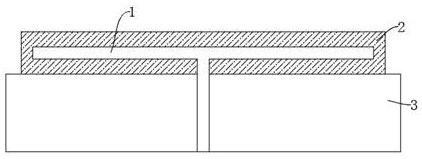
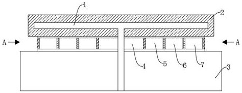
[0016] refer to figure 2 and 3 , is the first embodiment of the present invention, this embodiment provides a piezoelectric electrostatic chuck, including an electrode 1, a ceramic plate 2 and an aluminum substrate 3, the ceramic plate 2 is arranged on the aluminum substrate 3, and the ceramic plate 2 is Made of sintered aluminum nitride, the aluminum base 3 is where the radio frequency enters, the electrode 1 is set on the ceramic plate 2 and the aluminum base 3, the electrode 1 is made of tungsten or titanium alloy, and the ceramic plate 2 and the aluminum base 3 are between A piezoelectric module is jointly provided, and the piezoelectric module is based on the capacitive response in the radio frequency circuit of the mechanical energy driving the electrode 1 to affect the plasma. The piezoelectric module includes a central piezoelectric module 4, an excessive piezoelectric module 5, and surrounding The piezoelectric module 6 and the edge piezoelectric module 7, the centr...
Embodiment 2
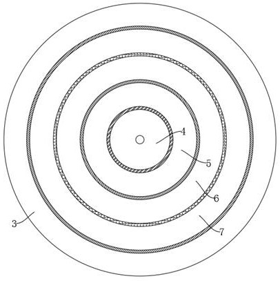
[0018] refer to figure 2 and 3 , is the second embodiment of the present invention. This embodiment is based on the previous embodiment. Specifically, the central piezoelectric module 4, the excessive piezoelectric module 5, the surrounding piezoelectric modules 6 and the edge piezoelectric modules 7 are all for the ring. The annular central piezoelectric module 4 , the excessive piezoelectric module 5 , the surrounding piezoelectric modules 6 and the edge piezoelectric modules 7 are more regular in shape and conform to the shape of the electrostatic chuck.
[0019] The central piezoelectric module 4 , the excessive piezoelectric module 5 , the surrounding piezoelectric modules 6 and the edge piezoelectric modules 7 are all arranged concentrically. The central piezoelectric module 4 , the excessive piezoelectric module 5 , the peripheral piezoelectric modules 6 and the edge piezoelectric modules 7 arranged concentrically between the ceramic plate 2 and the aluminum substrat...
Embodiment 3
[0023] refer to figure 2 and 3 , which is the third embodiment of the present invention. This embodiment is based on the above two embodiments. When in use, the piezoelectric electrostatic chuck controls the central piezoelectric module 4 through separate hydraulic control systems. , excessive piezoelectric module 5, peripheral piezoelectric module 6, edge piezoelectric module 7, so that the central piezoelectric module 4, the excessive piezoelectric module 5, the peripheral piezoelectric module 6 or the edge piezoelectric module 7 Under the control of the corresponding hydraulic control system, the central piezoelectric module 4, the excessive piezoelectric module 5, the surrounding piezoelectric modules 6 or the edge piezoelectric modules 7 are mechanically The capacitive response in the radio frequency circuit in the drive electrode 1 can affect the plasma, thereby making the radio frequency circuit more stable, so as to achieve the effect of continuous stability when the...
PUM
 Abstract
Description
Claims
Application Information
 - R&D Engineer
- R&D Manager
- IP Professional
- Industry Leading Data Capabilities
- Powerful AI technology
- Patent DNA Extraction
Browse by: Latest US Patents, China's latest patents, Technical Efficacy Thesaurus, Application Domain, Technology Topic, Popular Technical Reports.
© 2024 PatSnap. All rights reserved.Legal|Privacy policy|Modern Slavery Act Transparency Statement|Sitemap|About US| Contact US: help@patsnap.com