
Lofting device of rocking furnace

A technology for a swing furnace and a furnace body, applied in the field of swing furnaces, can solve the problems of difficulty in judging firm fixation, low efficiency, waste of chemical samples, etc., so as to improve work efficiency and equipment utilization, simplify operation steps, and solve the effects of time-consuming and labor-intensive

Pending Publication Date: 2022-07-15
PREGIS NEW MATERIALS (SHENZHEN) PTE LTD
View PDF0 Cites 0 Cited by
  • Summary
  • Abstract
  • Description
  • Claims
  • Application Information

AI Technical Summary

Problems solved by technology

At present, the common swing furnace lofting device is generally a high temperature resistant stainless steel round rod. When in use, there are generally two ways to fix the quartz test tube: one is to tie the quartz test tube to the stainless steel round rod with iron wire. This method depends on the length of the rod. And the size of the test tube, you can fix multiple quartz test tubes at a time, but the disadvantage is that it is time-consuming and laborious (need to wind multiple layers of iron wire), and it is difficult to judge whether it is fixed firmly (whether it will be loose during the swing process), and if you use too much force during the binding process, It is easy to crush the relatively thin and fragile quartz test tube, resulting in waste of chemical samples; the second is to penetrate the end of the stainless steel round rod into the quartz test tube, withstand the quartz plug inside the test tube, and then place the other end of the test tube against the furnace wall , so as to fix the quartz test tube. Although this method is relatively reliable and time-saving and labor-saving, the disadvantage is that only one quartz test tube can be fixed at a time, and the efficiency is extremely low, and the diameter of the stainless steel rod must not be greater than the inner diameter of the quartz test tube. Fixable quartz cuvettes are limited in size

Method used


Image

  • Lofting device of rocking furnace
  • Lofting device of rocking furnace
  • Lofting device of rocking furnace

Examples


Embodiment Construction

[0036] In order to have a clearer understanding of the technical features, purposes and effects of the present invention, the specific embodiments of the present invention will now be described in detail with reference to the accompanying drawings.

[0037] A component is referred to as being "fixed to" or "disposed on" another component, and it can be directly or indirectly located on the other component. When an element is referred to as being "connected to" another element, it can be directly or indirectly connected to the other element.

[0038] Terms "top", "bottom", "left", "right", "front", "back", "vertical", "horizontal", "top", "bottom", "inside", "outer", etc. The orientation or location indicated is based on the orientation or location shown in the drawings.

[0039] The terms "axial" and "radial" refer to the length direction of the entire device or component as "axial", and the direction perpendicular to the axial direction is "radial".

[0040] The terms "firs...


PUM


Abstract

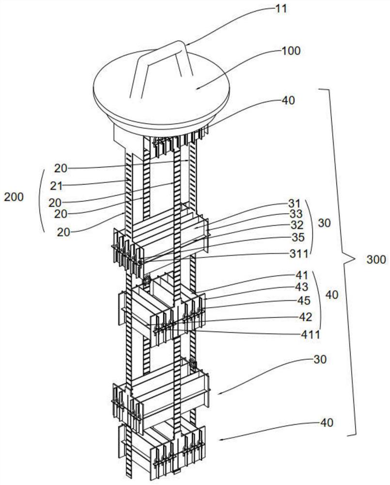
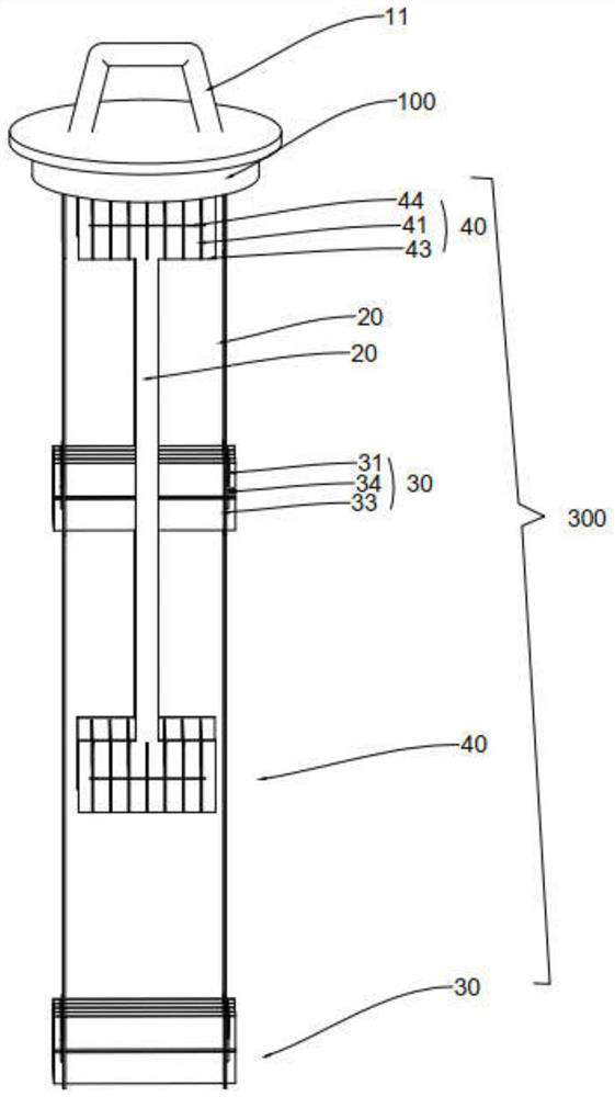
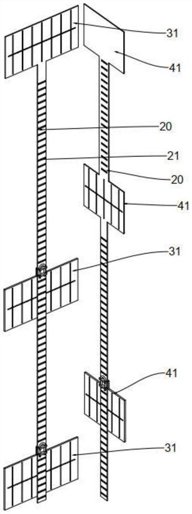
The invention discloses a lofting device of a rocking furnace. The lofting device comprises a top cover, a connecting assembly arranged at the bottom of the top cover and a lofting mechanism, the lofting mechanism comprises at least one group of first lofting assembly and second lofting assembly which are arranged at intervals in the axial direction; the first lofting assembly comprises at least two first clamping plates which are arranged in parallel at intervals to form at least one first lofting accommodating position; the second lofting assembly comprises at least two second clamping plates which are arranged in parallel at intervals to form at least one second lofting containing position, the first lofting containing position and the second lofting containing position are provided with a first limiting piece and a second limiting piece respectively, and the arrangement directions of the first lofting containing position and the second lofting containing position are different so that the projections of the first lofting containing position and the second lofting containing position in the axial direction can intersect. The crossed part of the axial projection is matched with the first limiting piece and the second limiting piece to form a plurality of lofting spaces; the lofting device is firm in lofting, a plurality of sample tubes can be placed, the lofting device can adapt to the sample tubes of different sizes and specifications, and the working efficiency and the equipment utilization rate are improved.

Description

technical field [0001] The invention relates to the technical field of swing furnaces, in particular to a setting-out device of a swing furnace. Background technique [0002] Swing furnace is a special high-temperature equipment specially developed for colleges and universities, scientific research institutes and industrial and mining enterprises to sinter, melt, analyze and detect metal, non-metal and other compound materials in atmosphere or vacuum state. The system is integrated with the box-type furnace body. In the furnace body, resistance wires are generally used as heating elements, and corundum tubes or quartz glass tubes are used to cross the middle of the furnace body as the furnace chamber. The heating elements and the furnace chamber are parallel and evenly distributed outside the furnace chamber. When using the swing furnace, the chemical sample is first sealed in a quartz test tube (the sealing method is generally to melt a cylindrical quartz glass plug inside ...

Claims


Application Information

Patent Timeline
Patent Type & Authority Applications(China)
IPC IPC(8): F27B17/02F27D5/00
CPCF27B17/02F27D5/0006
Inventor 郑俊彬汤弢
Owner PREGIS NEW MATERIALS (SHENZHEN) PTE LTD
Learn More