Vertical shaft construction device and method
A construction device and shaft technology, which is applied to shaft equipment, earthwork drilling, wellbore lining, etc., can solve the problems of difficulty in ensuring the same reference of the formwork, need to re-center, deviation of well wall construction and standard requirements, etc., and achieve a high degree of completion. , The effect of high construction efficiency and simple construction
- Summary
- Abstract
- Description
- Claims
- Application Information
AI Technical Summary
Problems solved by technology
Method used
Image

Examples
Embodiment 1
[0045] Embodiment 1, this embodiment aims to provide a shaft construction device, which is mainly used for the well wall pouring operation of the shaft. When supporting the existing formwork structure, the formwork needs to be re-centred every time it is used, which is difficult to ensure. Each template is on the same benchmark, resulting in the problem of deviation between the construction of the shaft wall and the standard requirements. This embodiment provides a shaft construction device.
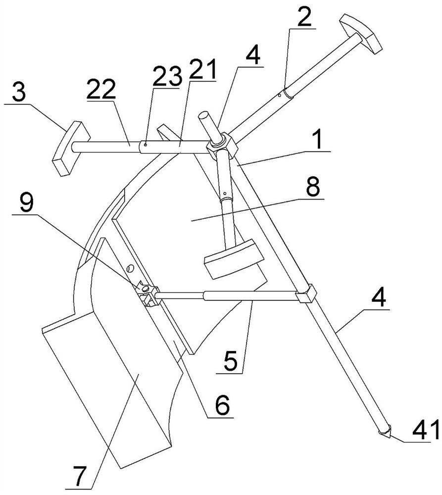
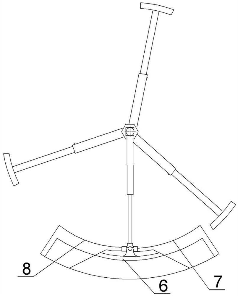
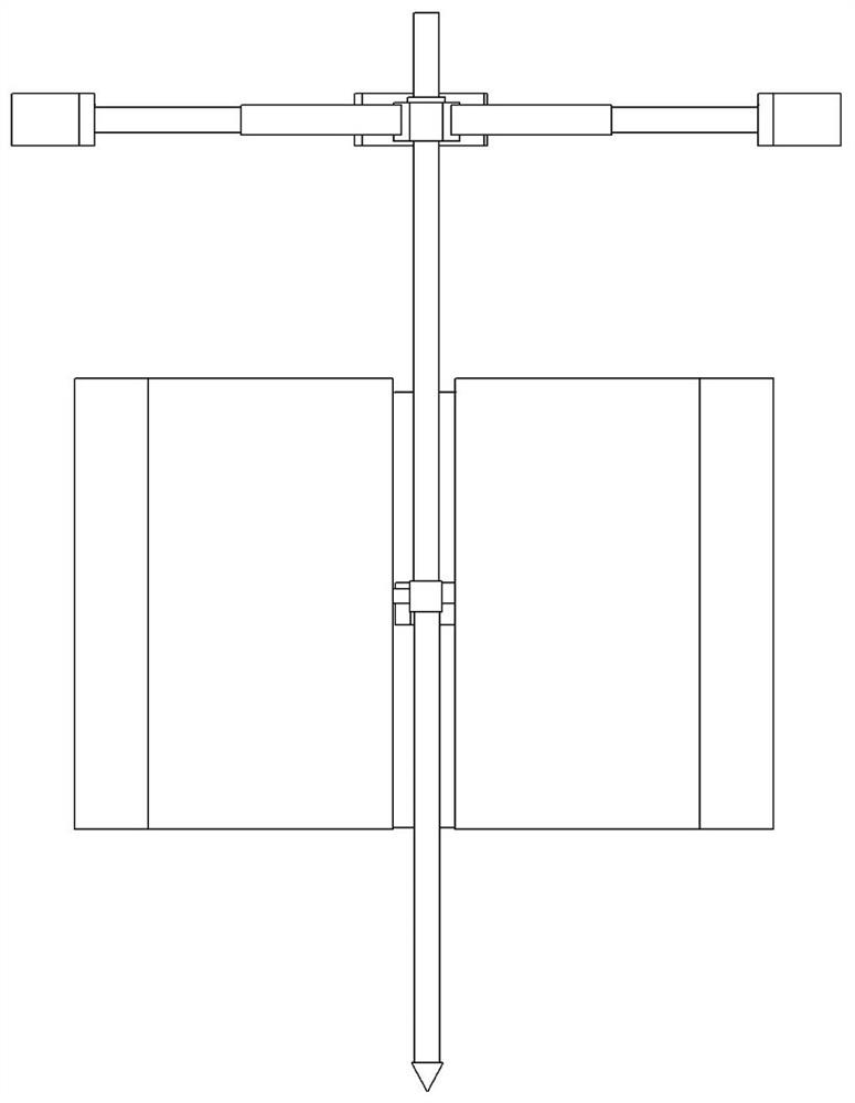
[0046] like Figure 1-3 In this example, a shaft construction device is shown, including a center sleeve 1, a positioning mechanism, a telescopic mechanism and a combined template. In this embodiment, the center sleeve 1 is used as a fixed foundation, and its basic structure is a cylindrical structure, and a positioning structure is arranged on its upper part. , the lower part is arranged with a telescopic structure.
[0047] In the specific structure, the positioning mechanism includes...
Embodiment 2
[0068] Embodiment 2, this embodiment is basically the same as Embodiment 1, the difference is that this embodiment provides a positioning rod structure of another structure.
[0069] like Figure 10 The positioning rod 2 includes a sliding sleeve 26, a support rod 28 and a swing rod 27, the inner end of the swing rod 27 is hinged on the center sleeve 1, the sliding sleeve 26 is slidably sleeved on the center sleeve 1, and a lock is provided on its side. The two ends of the support rod 28 are respectively hinged to the side of the sliding sleeve and the middle of the swing rod, and the end of the swing rod is provided with a positioning block.
[0070] In this embodiment, the sliding sleeve is used to lift the pendulum rod synchronously, that is, the pendulum rod can be expanded synchronously, thereby realizing the purpose of rapid centering. Compared with the structure in Embodiment 1, the operation is simpler and the retracted state is smaller, which is convenient for Transf...
Embodiment 3
[0071] Embodiment 3, this embodiment is basically the same as Embodiment 1, the difference is that this embodiment provides another structure of the power telescopic rod structure.
[0072] In this embodiment, the power telescopic rod 5 includes an inner thread cylinder 16 , an outer thread cylinder 15 , an adjusting wire 17 and a stabilizing sleeve 18 . The opposite reverse thread, the two ends of the adjusting wire 17 are reverse threads, and are respectively screwed into the inner thread barrel and the outer thread barrel, the stabilizing sleeve 18 is slidably sleeved on the outside of the inner thread barrel, and is fixed on the center sleeve by a reinforcing rod On the rotating sleeve 20 on the upper part, the rotating sleeve 20 is rotatably sleeved on the center sleeve.
[0073] like Figure 5-6 It is shown in the figure that the stabilizing sleeve 18 and the inner threaded barrel 16 are sliding and non-rotatable sleeve structures, so as to avoid the rotation of the inn...
PUM
 Abstract
Description
Claims
Application Information
 - R&D
- Intellectual Property
- Life Sciences
- Materials
- Tech Scout
- Unparalleled Data Quality
- Higher Quality Content
- 60% Fewer Hallucinations
Browse by: Latest US Patents, China's latest patents, Technical Efficacy Thesaurus, Application Domain, Technology Topic, Popular Technical Reports.
© 2025 PatSnap. All rights reserved.Legal|Privacy policy|Modern Slavery Act Transparency Statement|Sitemap|About US| Contact US: help@patsnap.com