
Self-protection floor spring

A floor spring and elastic mechanism technology, applied in the field of floor springs, can solve the problems of inflexible adjustment of door stability, high degree of friction of structural parts, and inflexible use, etc., to achieve reduced friction, flexible use, and comprehensive switching effects Effect

Inactive Publication Date: 2022-07-15
南京旭科蓝镇科技有限公司
View PDF0 Cites 0 Cited by
  • Summary
  • Abstract
  • Description
  • Claims
  • Application Information

AI Technical Summary

Problems solved by technology

Because the worm gear can rotate forward and reverse, the floor spring can be used for two-way open doors, while the door closer can only be used for one-way open doors. There are limitations in use, and the door body can only be fully opened and fully closed. The state is not flexible enough to use, and the door cannot be positioned after opening to the specified opening degree. Secondly, the stability of the door cannot be adjusted flexibly after the door is opened. In addition, due to the setting of the worm gear and other mechanisms, the friction degree of the structural parts is large. Moreover, most of the friction parts are teeth, which are prone to breakage and damage, which brings inconvenience

Method used


Image

  • Self-protection floor spring
  • Self-protection floor spring
  • Self-protection floor spring

Examples


Embodiment Construction

[0027] The following description serves to disclose the invention to enable those skilled in the art to practice the invention. The preferred embodiments described below are given by way of example only, and other obvious modifications will occur to those skilled in the art.

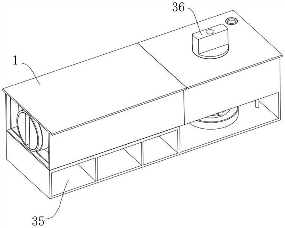
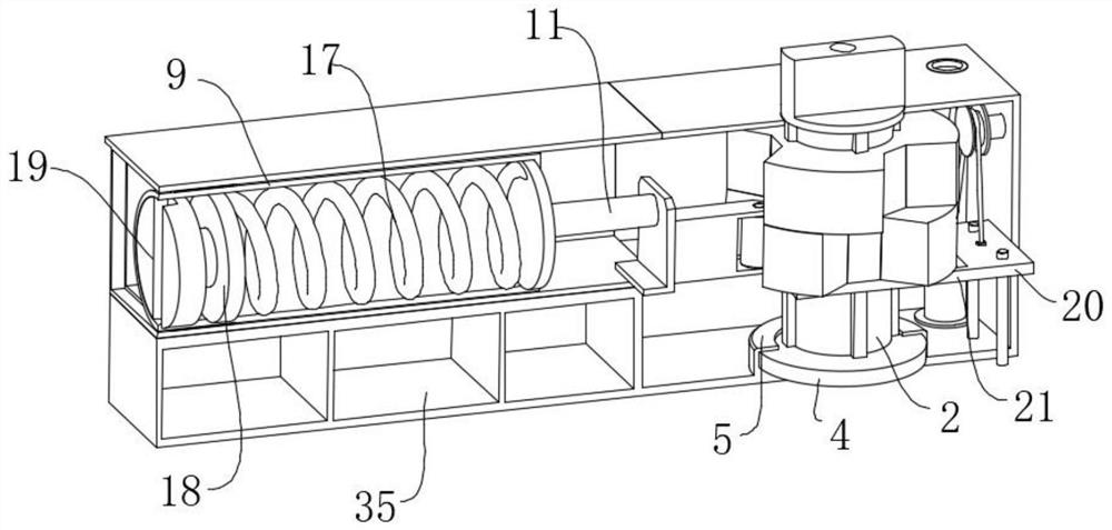
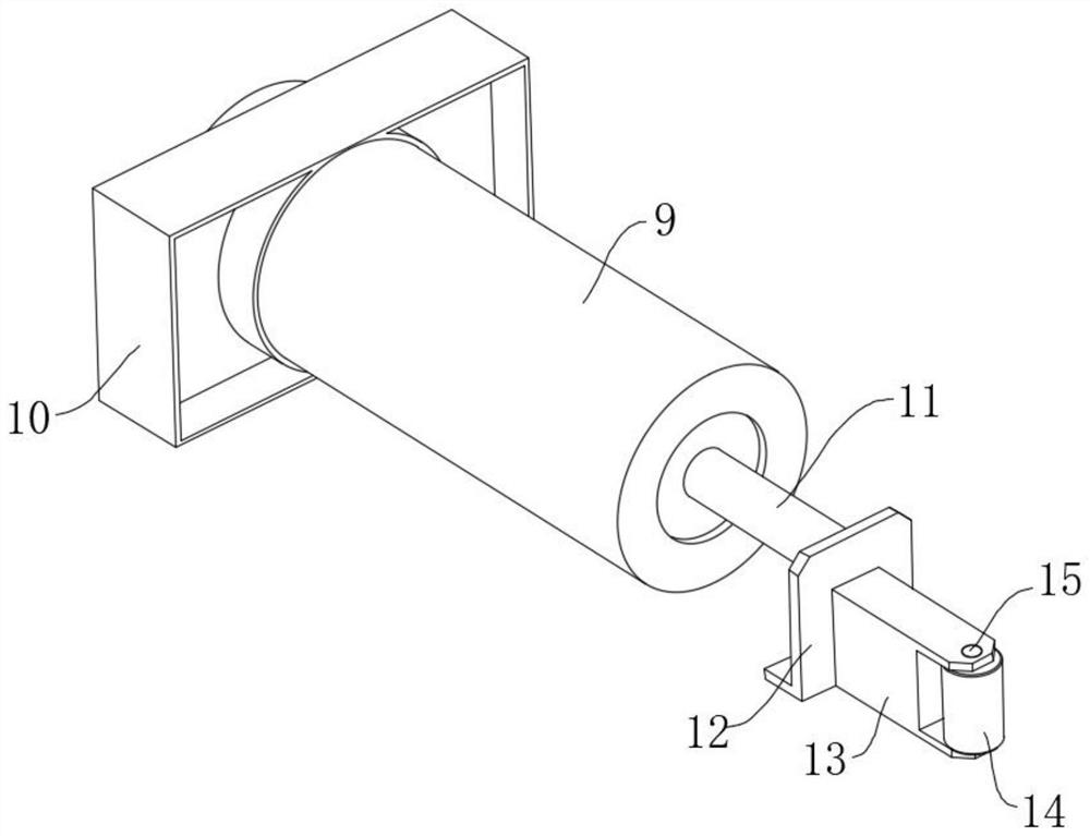
[0028] like Figure 1-Figure 7 The shown self-protection type floor spring includes a casing 1, the inner side of the casing 1 is provided with a rotating shaft 2 extending vertically, the lower end of the rotating shaft 2 is rotatably matched with the inner bottom surface of the casing 1, and the upper end of the rotating shaft 2 extends To the outside of the housing 1 and provided with a connecting portion, the outer surface of the rotating shaft 2 is vertically slidably sleeved with a first baffle plate 6 and a second baffle plate 7 , and the outer surfaces of the first baffle plate 6 and the second baffle plate 7 are opened There are unequal number of landing slots 8, a connecting block 13 is arrang...


PUM


Abstract

The invention relates to the field of floor springs, in particular to a self-protection floor spring which comprises a shell, a rotating shaft extending in the vertical direction is arranged on the inner side of the shell, the lower end of the rotating shaft is in rotating fit with the bottom face of the inner side of the shell, and the upper end of the rotating shaft extends out of the shell and is provided with a connecting part. The outer surface of the rotating shaft is slidably sleeved with a first stopping disc and a second stopping disc in the vertical direction, the outer surfaces of the first stopping disc and the second stopping disc are provided with halfpace grooves of different numbers, a connecting block is arranged on the inner side, close to one side of the second stopping disc, of the shell, one end of the connecting block is movably clamped into the inner side of each halfpace groove, and the other end of the connecting block is movably clamped into the halfpace groove. The structure of a worm gear in a traditional floor spring is changed, rotation of the floor spring is smoother, the friction effect is reduced, damage is not likely to happen, the service life is prolonged, after the floor spring is matched with a door to be installed, the rotation angle of the door each time can be adjusted, the damping feeling during door pushing can be changed, and the using effect is more comprehensive.

Description

technical field [0001] The invention relates to the field of floor springs, in particular to a self-protection type floor spring. Background technique [0002] The floor spring is a kind of door closer, and the compression spring device of the floor spring in the prior art is a worm gear instead of a gear and a rack. Because the worm gear can rotate in forward and reverse directions, the floor spring can be used for doors that open in both directions, while the door closer can only be used for doors that open in one direction. There are limitations in use, and the door can only be fully opened and fully closed. It is not flexible enough to use, and the door cannot be opened to the specified opening degree and then positioned. Secondly, the stability of the door cannot be adjusted flexibly after the door is opened. In addition, due to the setting of the worm gear and other mechanisms, the friction degree of the structural parts is large. In addition, the friction part is mos...

Claims


Application Information

Patent Timeline
Patent Type & Authority Applications(China)
IPC IPC(8): E05F1/12
CPCE05F1/1246E05Y2900/132
Inventor 吴雨婷
Owner 南京旭科蓝镇科技有限公司
Learn More