
Waste incineration power plant slag feeding device and slag comprehensive utilization system

A technology of waste incineration and power plant, applied in loading/unloading, transportation and packaging, solid separation, etc., can solve the problems of inaccurate loading time, secondary environmental pollution, uneven discharge, etc., to avoid excessive loading. Too much or too little, avoid secondary pollution, improve the effect of service life

Pending Publication Date: 2022-07-15
赵志强
View PDF9 Cites 0 Cited by
  • Summary
  • Abstract
  • Description
  • Claims
  • Application Information

AI Technical Summary

Problems solved by technology

[0003] The slag produced after incineration for power generation is cooled and stored in the slag storage tank, and then transported by the transport vehicle to the outside of the power plant for comprehensive utilization or landfill. The loading time is uncontrollable, usually judged according to manual experience, but the manual judgment of the loading time is inaccurate, it is easy to load too little or too much material, resulting in a decrease in work efficiency, and too much material is likely to cause slag to spill, causing secondary environmental pollution , The peculiar smell brought by the spilled slag has affected the working environment, and working for a long time in a harsh environment will affect the physical and mental health of the staff. Therefore, those skilled in the art provide a slag feeding device for waste incineration power plants to solve the above background questions raised in technology

Method used


Image

  • Waste incineration power plant slag feeding device and slag comprehensive utilization system
  • Waste incineration power plant slag feeding device and slag comprehensive utilization system
  • Waste incineration power plant slag feeding device and slag comprehensive utilization system

Examples


Embodiment Construction

[0034] The technical solutions in the embodiments of the present invention will be clearly and completely described below with reference to the accompanying drawings in the embodiments of the present invention; obviously, the described embodiments are only a part of the embodiments of the present invention, not all of the embodiments. The embodiments of the present invention, and all other embodiments obtained by those of ordinary skill in the art without creative work, fall within the protection scope of the present invention.

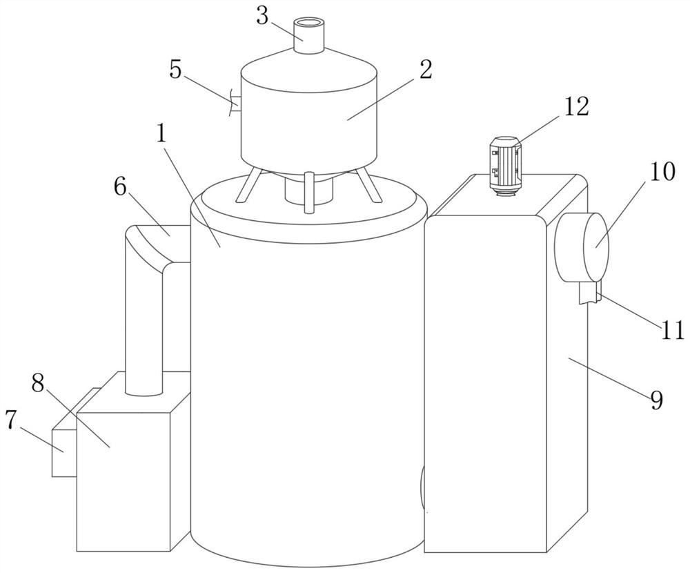
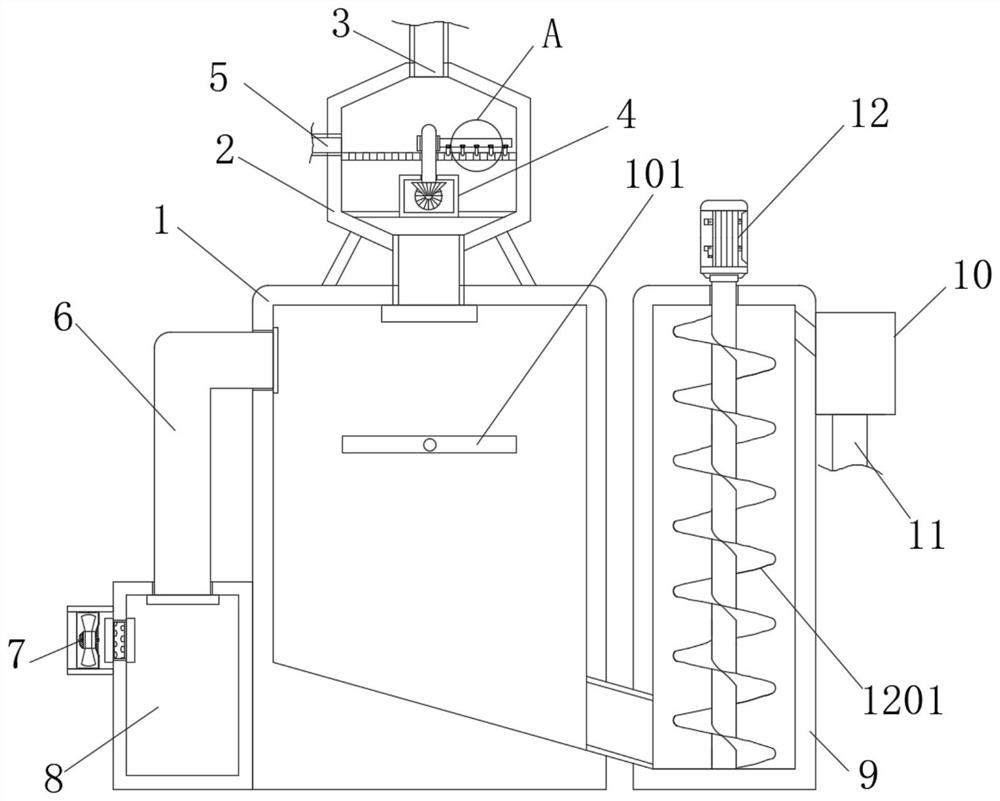
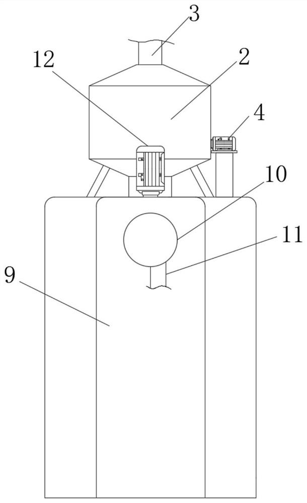
[0035] see Figure 1-7 , in the embodiment of the present invention, a waste incineration power plant slag feeding device includes a slag storage tank 1, the top of the slag storage tank 1 is communicated with a pretreatment box 2, and the top of the pretreatment box 2 is communicated with a feeding pipe 3, The surface of the pretreatment box 2 is provided with a miscellaneous discharge pipe 5, and the back of the pretreatment box 2 is provided with a...


PUM


Abstract

The invention discloses a waste incineration power plant slag feeding device and a comprehensive slag utilization system, and belongs to the technical field of waste incineration slag treatment.The waste incineration power plant slag feeding device is characterized by comprising a slag storage tank, the top of the slag storage tank communicates with a pretreatment box, and the top of the pretreatment box communicates with a feeding pipe; an impurity discharging pipe is arranged on the surface of the pretreatment box, an anti-blocking mechanism is arranged on the back face of the pretreatment box, the anti-blocking mechanism penetrates through the pretreatment box and extends into the pretreatment box, and a filtering mechanism is arranged on the left side of the slag storage tank. According to the slag loading device, slag loading is uniform and orderly, workers can better operate according to loading conditions, the situation that too much or too little loading is caused by traditional judgment according to working experience is avoided, the working efficiency is improved, meanwhile, secondary pollution caused by slag scattering due to too much loading is avoided, the working environment is improved, and the labor intensity of workers is reduced. And the physical and psychological health of workers is protected.

Description

technical field [0001] The invention relates to the technical field of waste incineration slag treatment, and more particularly, to a slag feeding device and a slag comprehensive utilization system in a waste incineration power plant. Background technique [0002] In people's daily life, a large amount of garbage is inevitably generated. If these wastes are not treated effectively, it will greatly affect people's living environment and even pose a threat to people's health. Incineration is one of the main ways to dispose of garbage, but in the process of incinerating garbage, in addition to causing secondary environmental pollution, it will also cause waste of resources and energy. Therefore, in waste treatment, waste incineration can be used for power generation. The slag generated after incineration and power generation can be transported to outside the power plant for comprehensive utilization or landfill, turning waste into treasure to reduce pollution. [0003] The sl...

Claims


Application Information

Patent Timeline
Patent Type & Authority Applications(China)
IPC IPC(8): B65G67/06B65G65/46B65G69/12B65G69/18B07B1/50B07B1/46B07B1/04
CPCB65G67/06B65G65/46B65G69/12B65G69/181B07B1/04B07B1/46B07B1/50
Inventor 赵志强刘鹏宋桐桐
Owner 赵志强
Learn More