Low-flow-resistance under-pressure plugging fluid connector

A low flow resistance, connector technology, applied in couplings, mechanical equipment, etc., can solve problems such as product failure, leakage, and seal failure, and achieve the effects of reducing eddy current interference, increasing fluid flux, and reducing flow resistance

Pending Publication Date: 2022-07-12
SUZHOU HUAZHAN SPACE APPLIANCE
View PDF0 Cites 0 Cited by
  • Summary
  • Abstract
  • Description
  • Claims
  • Application Information

AI Technical Summary

Problems solved by technology

[0004] 1. The flow resistance of the fluid connector is relatively large, and the heat dissipation effect is not ideal
Especially in the range where the axial floating ratio is large, it is not easy to meet the low flow resistance
[0005] 2. During the process of opening or closing the flow channel of the fluid connector, the O-ring is affected by the pressure of the water flow and is easily washed off and deformed, resulting in seal failure;
[0006] 3. Existing fluid connectors use a single sealing component as the plug-in end and the socket-in-connection end to protect the sealing parts. The sealing component is installed in the plug in an axially movable manner through a spring, so as to realize the free state when the spring pushes Under the action, the fluid channel of the plug is blocked, and when the plug and socket are inserted, they move axially and form a flow channel with the inner wall of the housing for the liquid to pass through. When the flow channel is opened, the O-ring in the center of the fluid channel of the plug / socket is not blocked Protection, under the impact of high-speed liquid, deformation, shedding, adhesion of impurities lead to leakage and product failure

Method used


Image

  • Low-flow-resistance under-pressure plugging fluid connector
  • Low-flow-resistance under-pressure plugging fluid connector
  • Low-flow-resistance under-pressure plugging fluid connector

Examples


Embodiment Construction

[0044] In order to more fully understand the technical content of the present invention, the technical solutions of the present invention are further introduced and described below with reference to specific embodiments, but are not limited thereto.

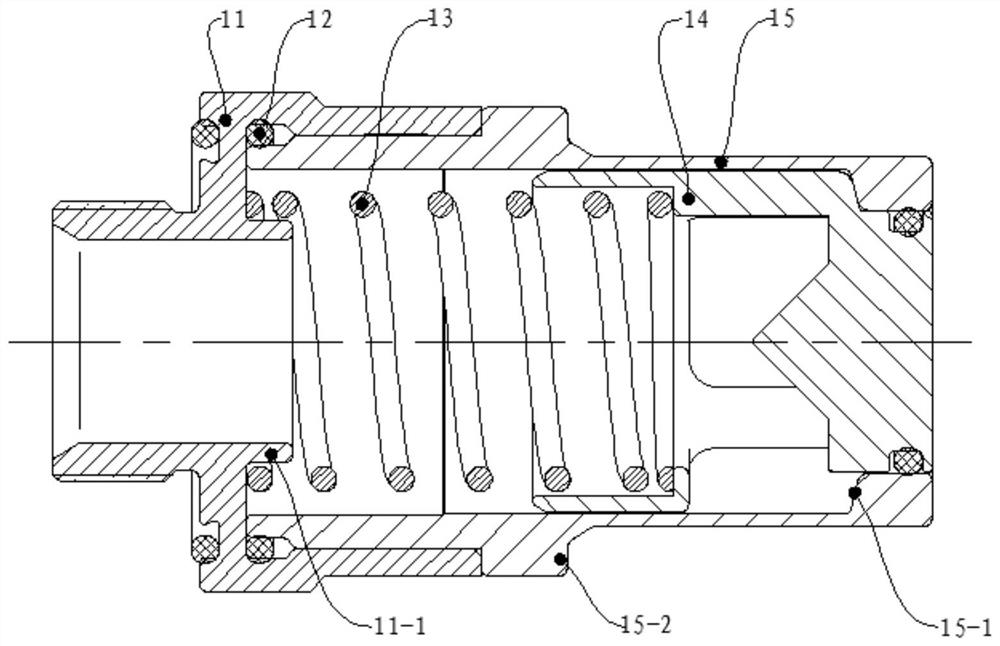
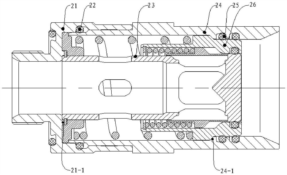
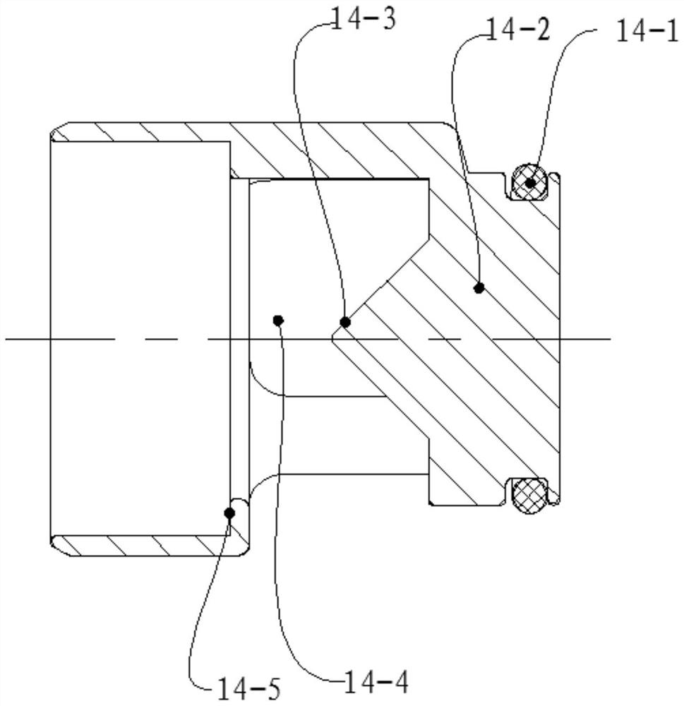
[0045] combine Figure 1 to Figure 5 Further describe a low flow resistance band pressure plug-in fluid connector provided by the present invention, including: a plug 1, a first installation shell 11, a first spring positioning portion 11-1, a first sealing ring 12, a first spring 13, The first axial sliding seal assembly 14, the second sealing ring 14-1, the sliding seal 14-2, the first diverting structure 14-3, the first flow hole 14-4, the first spring limiting part 14-5 , the plug-in housing 15, the first limit part 15-1, the insertion limit part 15-2, the socket 2, the second installation shell 21, the anti-drop structure 21-1, the fourth seal ring 22, the axial fixed seal Assembly 23, axial seal assembly fixing element 23-...


PUM


Abstract

The invention discloses a low-flow-resistance pressurized plugging fluid connector which comprises a plug and a socket matched with the plug, and the front end of the plug and the front end of the socket are plugging ends. The plug comprises a first mounting shell, a first sealing ring, a first spring, a first axial sliding sealing assembly and a plug-in shell; the first axial sliding sealing assembly is assembled at the front end in the first mounting shell in a sliding manner; the socket comprises a second mounting shell, a third sealing ring group, a fourth sealing ring, a fifth sealing ring, an axial fixed sealing assembly, a third spring, a guide shell and a second axial sliding sealing assembly; by means of the structural design, in the working process, the sealing ring at the valve element at one end of the switch flow channel is exposed in fluid, and the sealing ring at the valve element at the other end is not exposed in the fluid, so that the sealing ring at the position cannot be washed away when the flow speed of the fluid is large; the service life of the sealing ring is prolonged, and the number of times of under-pressure plugging and unplugging of the connector is increased.

Description

technical field [0001] The invention belongs to the technical field of fluid connectors, and in particular relates to a low-flow resistance plug-in-pull fluid connector with pressure. Background technique [0002] With the continuous development of electronic components in equipment towards high frequency, high density and high integration, the problem of how to achieve efficient heat dissipation in equipment has become more and more prominent. Liquid cooling technology has become the preferred solution to this problem. Liquid cooling technology has been widely used in aviation, aerospace, electronics, ships, communications, wind power, electric vehicles, data centers and other fields. [0003] With the increasing development of technology, electronic equipment tends to be highly reliable, and a highly reliable fluid connector is urgently needed to realize the transmission of fluid between the cooled module and the chassis. However, such existing connectors have the followin...

Claims


Application Information

Patent Timeline
Patent Type & Authority Applications(China)
IPC IPC(8): F16L37/367
CPCF16L37/367
Inventor 李岩张杰何仲祺黄良用
Owner SUZHOU HUAZHAN SPACE APPLIANCE
Why Eureka
Try Eureka