Steam pipeline butterfly valve with pressure relief function

A technology of steam pipes and butterfly valves, which is applied in the field of butterfly valves, can solve problems such as time-consuming maintenance, reduced work efficiency, and increased air pressure, and achieves the effects of avoiding pipeline damage, saving costs and time, and being easy to use

Pending Publication Date: 2022-07-12
BAOYI GROUP
View PDF0 Cites 0 Cited by
  • Summary
  • Abstract
  • Description
  • Claims
  • Application Information

AI Technical Summary

Problems solved by technology

[0004] The purpose of the present invention is to solve the problem that when the butterfly valve in the prior art is in use, the air pressure in the pipeline may increase. If the pressure is not released in time, it will easily lead to pipeline rupture and gas leakage, which will take a lot of time. Maintenance, the shortcomings of greatly reducing work efficiency, and a steam pipeline butterfly valve with pressure relief function is proposed

Method used


Image

  • Steam pipeline butterfly valve with pressure relief function
  • Steam pipeline butterfly valve with pressure relief function
  • Steam pipeline butterfly valve with pressure relief function

Examples


Embodiment 1

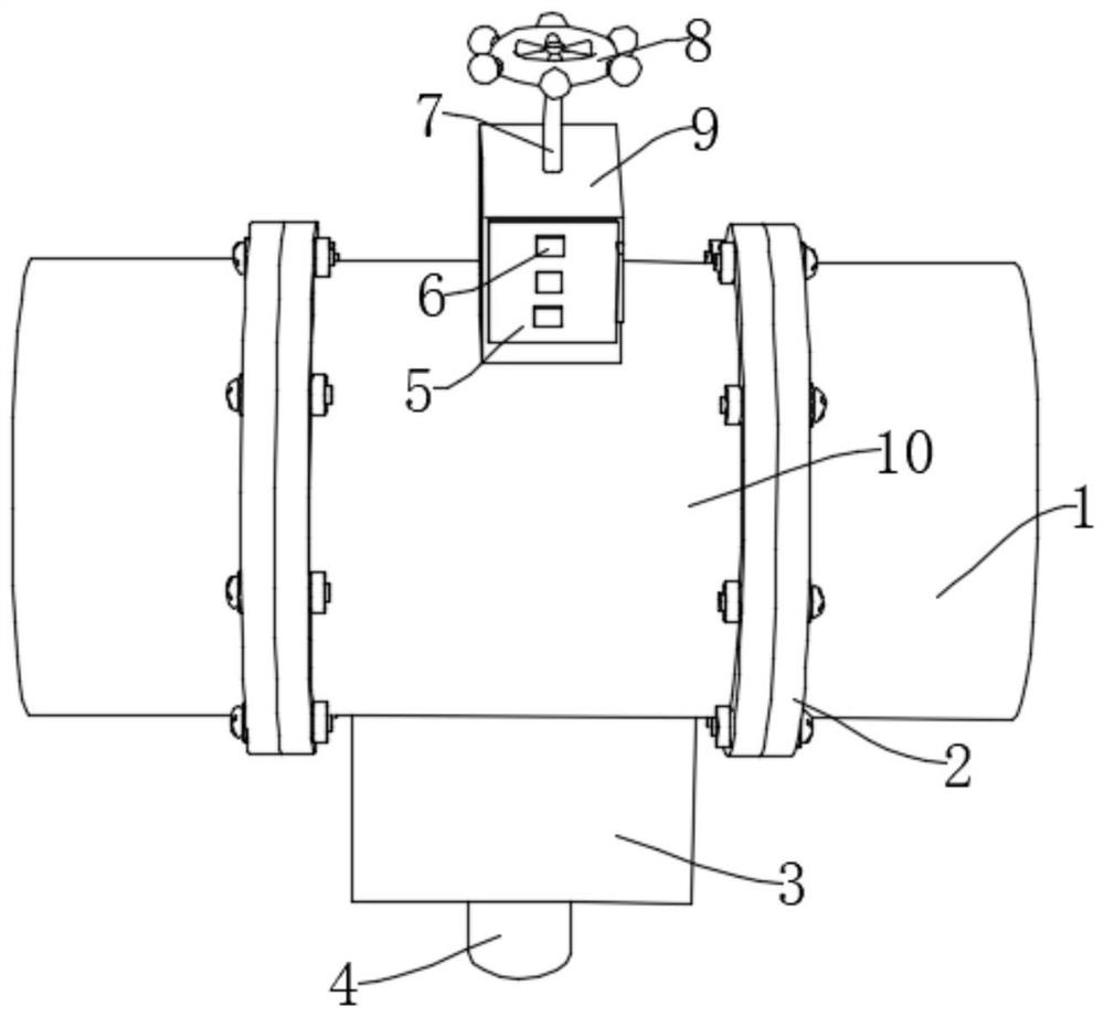
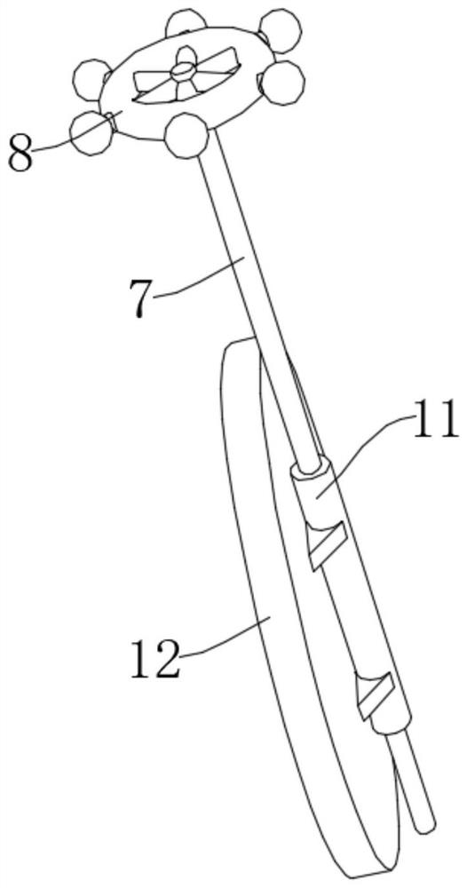
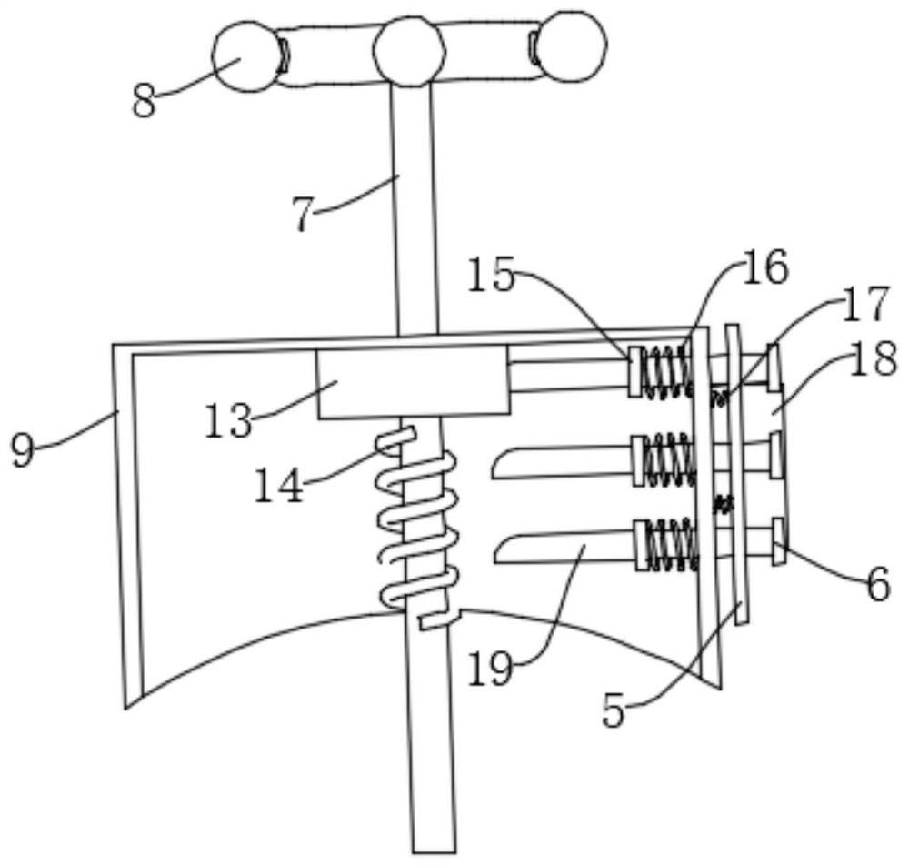
[0031] refer to Figure 1-Figure 7 , a steam pipeline butterfly valve with a pressure relief function, comprising a butterfly valve body 10, both ends of the butterfly valve body 10 are fixedly connected with a connecting pipe 1, the top of the butterfly valve body 10 is fixedly connected with a second rectangular box 9, the second rectangular box The inner wall of 9 is slidably connected with a sliding block 13, the inner wall of the sliding block 13 rotates through a rotating shaft 7, the top of the rotating shaft 7 penetrates the second rectangular box 9 and is fixedly connected with a handle 8, and the outer wall of the rotating shaft 7 is slidably provided with a fixed cylinder 11, One side of the fixing cylinder 11 is fixedly connected with the valve flap 12 used in cooperation with the butterfly valve body 10, and one side of the second rectangular box 9 is provided with a fixing component for fixing the sliding block 13;

[0032] The bottom of the butterfly valve body ...

Embodiment 2

[0035] refer to Figure 1-Figure 7 , a steam pipeline butterfly valve with a pressure relief function, comprising a butterfly valve body 10, both ends of the butterfly valve body 10 are fixedly connected with a connecting pipe 1, the top of the butterfly valve body 10 is fixedly connected with a second rectangular box 9, the second rectangular box The inner wall of 9 is slidably connected with a sliding block 13, the inner wall of the sliding block 13 rotates through a rotating shaft 7, the top of the rotating shaft 7 penetrates the second rectangular box 9 and is fixedly connected with a handle 8, and the outer wall of the rotating shaft 7 is slidably provided with a fixed cylinder 11, One side of the fixed cylinder 11 is fixedly connected with the valve flap 12 used in conjunction with the butterfly valve body 10 , one side of the second rectangular box 9 is provided with a fixed component for fixing the sliding block 13 , and the fixed component includes a sliding through th...


PUM


Abstract

The invention belongs to the field of butterfly valves, particularly relates to a steam pipeline butterfly valve with a pressure relief function, and aims to solve the problems that when an existing butterfly valve is used, due to the fact that air pressure in a pipeline is possibly increased, if pressure is not relieved in time, pipeline breakage, gas leakage and the like are easily caused, and a large amount of time needs to be consumed for maintenance; according to the technical scheme, the butterfly valve comprises a butterfly valve body, the two ends of the butterfly valve body fixedly communicate with connecting pipes, the top of the butterfly valve body is fixedly connected with a second rectangular box, and the inner wall of the second rectangular box is slidably connected with a sliding block. By arranging the first pressure relief assembly, the pressure relief function can be achieved when the air pressure in the pipeline is increased, when the air pressure is increased to exceed a threshold value, the device is protected through the second pressure relief assembly, the device is prevented from being damaged, meanwhile, the cost and time brought by maintenance are greatly saved, and the working efficiency is improved.

Description

technical field [0001] The invention relates to the technical field of butterfly valves, in particular to a steam pipeline butterfly valve with a pressure relief function. Background technique [0002] Butterfly valve, also known as flap valve, is a kind of regulating valve with simple structure. Butterfly valve that can be used for on-off control of low-pressure pipeline medium means that the closing member (disc or butterfly plate) is a disc, which rotates around the valve shaft to achieve opening and closing. A valve that can be used to control the flow of various types of fluids such as air, water, steam, various corrosive media, mud, oil, liquid metal and radioactive media. It mainly plays the role of cutting and throttling on the pipeline. The butterfly valve opening and closing part is a disc-shaped butterfly plate, which rotates around its own axis in the valve body to achieve the purpose of opening and closing or adjustment. [0003] When the existing butterfly va...

Claims


Application Information

Patent Timeline
IPC IPC(8): F16K1/226F16K27/02F16K31/60F16L23/036
CPCF16K1/2261F16K27/0218F16K31/60F16L23/036
Inventor 夏胜建张晓忠黄晓云张晓秋戴雄浩张渊
Owner BAOYI GROUP
Why Eureka
Try Eureka