Water dance fountain mechanical arm device

A technology of mechanical arms and fountains, which is applied in the direction of spraying devices, liquid spraying devices, and spraying devices with movable outlets, etc. It can solve the problems of no interaction of fountain water shows, dull visual effects, and weak flexibility, etc., and achieve better economic effects. Excellent, efficient integrated control, flexible action effect

Pending Publication Date: 2022-07-12
北京中科恒业中自技术有限公司
View PDF1 Cites 0 Cited by
  • Summary
  • Abstract
  • Description
  • Claims
  • Application Information

AI Technical Summary

Problems solved by technology

However, in the existing fountain water show performances, the mechanical structure is often only used as a bracket (patent number CN206973205U). On the one hand, the mechanical structure only plays the role of supporting the performance equipment (LED screen), and does not participate in the performance itself, and does not move with the music. The visual effect is relatively dull, and the flexibility is not strong; on the other hand, there is no nozzle and other related fountain equipment installed on the mechanical mechanism, and there is no interaction with the main fountain water show, and the effect is not good

Method used


Image

  • Water dance fountain mechanical arm device
  • Water dance fountain mechanical arm device
  • Water dance fountain mechanical arm device

Examples


Embodiment 1

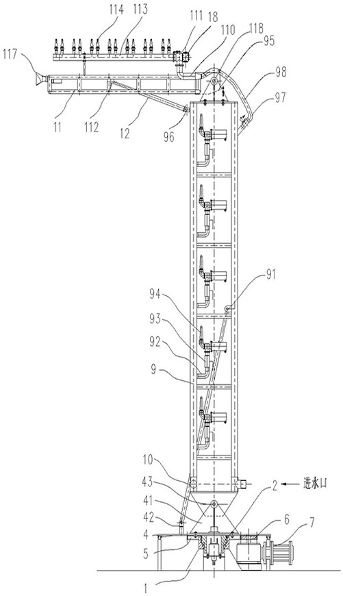
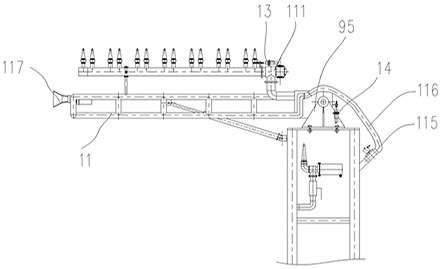
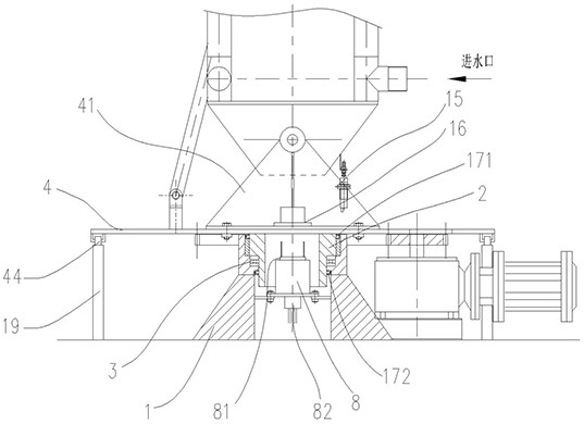
[0031] like Figure 1-2 As shown, the present invention adopts the following technical solutions, including: a primary arm 9, a secondary arm 11, a turntable 4, the upper end of the turntable 4 is provided with a first rotating support frame 41, the first rotating support frame 41 and the bottom of the primary arm 9 The upper end of the turntable 4 is also provided with a first-level hydraulic support seat 42, the middle of the first-level arm 9 is provided with a first thrust support frame 91, and the bottom end of the first-level hydraulic cylinder 10 is connected with the first-level hydraulic support seat 42, The output end is rotatably connected with the first thrust support frame 91, thereby driving the primary arm 9 to rotate around the first shaft 43; the top of the primary arm 9 is provided with a second rotating support frame 95, and the bottom end of the secondary arm 11 is supported by the second rotation The frame 95 is hinged through the second shaft 118; the upp...

Embodiment 2

[0045] like Figure 7 As shown, the present invention adopts the following technical solutions, including: a primary arm 9, a secondary arm 11, a turntable 4, the upper end of the turntable 4 is provided with a first rotating support frame 41, and the bottom end of the primary arm 9 is connected to the first rotating support frame 41 is hinged through the first rotating shaft 43; also includes the first waterproof motor 20, the first waterproof motor is installed on the turntable 4, and the output end of the first waterproof motor 20 is connected to the first rotating shaft 43 through the key rotation, and the first rotating shaft 43 and the first-level arm 9. The bottom end is fixedly connected, thereby driving the primary arm 9 to rotate around the first rotating shaft 43; also includes a second waterproof motor 21, the second waterproof motor is fixed on the primary arm 9, and its output end is connected to a driving gear 22 by a key, The driving gear 22 drives the driven g...


PUM


Abstract

A water dance fountain mechanical arm device comprises a first-stage arm, a second-stage arm and a rotating disc, a first rotating supporting frame is arranged at the upper end of the rotating disc, and the bottom end of the first-stage arm is hinged to the first rotating supporting frame; a second rotating support frame is arranged at the top end of the first-stage arm; the bottom end of the second-stage arm is hinged with the second rotating support frame; the first rotary driving mechanism is fixedly mounted at the upper end of the rotary table, and the output end of the first rotary driving mechanism is rotationally connected with the first-stage arm; the second rotary driving mechanism is fixedly mounted on the first-stage arm, and the output end of the second rotary driving mechanism is rotationally connected with the second-stage arm; the device further comprises a third rotary driving mechanism, the third rotary driving mechanism is connected with a driving gear, the driving gear is meshed with a driven gear fixedly connected to the rotary disc to drive the rotary disc to rotate, and the first rotary driving mechanism, the second rotary driving mechanism and the third rotary driving mechanism are all controlled by a computer through a control module.

Description

technical field [0001] The invention relates to the technical field of fountain equipment installation in fountain water show performances, in particular to a water dancing fountain mechanical arm device. Background technique [0002] The large and medium-sized mechanical structure moves continuously with the rhythm of the music, and the simultaneous performance with the fountain equipment can enhance the effect of the water show, so that the water type of the fountain presents a shocking effect of multi-dimensional and all-round perspectives. However, in the existing fountain water show performance, the mechanical structure is often only used as a bracket (patent number CN206973205U). On the one hand, the mechanical structure only plays the role of supporting the performance equipment (LED screen), and it does not participate in the performance itself, and does not move with the music. The visual effect is relatively rigid, and the flexibility is not strong; on the other ha...

Claims


Application Information

Patent Timeline
IPC IPC(8): B05B17/08B05B3/02B05B15/68
CPCB05B17/08B05B3/02B05B15/68Y02A40/22
Inventor 刘洪斌
Owner 北京中科恒业中自技术有限公司
Why Eureka
Try Eureka