
Manual back type shifting machine

A manual back-type and lift technology, which is applied in the fields of medical science, hospital beds, hospital equipment, etc., can solve the problem that the overhead electric lift is not suitable for small spaces, the comfort of the overhead electric lift is poor, High site requirements and other issues, to achieve the effect of rich overall functions, increased space utilization, and low production costs

Pending Publication Date: 2022-07-12
CRRC SHANDONG CO LTD
View PDF0 Cites 4 Cited by
  • Summary
  • Abstract
  • Description
  • Claims
  • Application Information

AI Technical Summary

Problems solved by technology

[0004] The existing sitting lifts have single functions and can only meet the short-distance lifting needs of the nursing staff
For disabled people with limited mobility and patients with limited lower limbs, the labor intensity of the nurses is high when the nurses carry them to the lift, and the comfort of the overhead electric lift is poor and the price is low. Expensive, and has high requirements for the site when moving
The sky-rail electric lift uses the strap to lift the nursing staff, and uses the slide rail to realize its shifting work. During the hoisting process, the sling acts on the inner thigh of the nursing staff, and the gravity will make the sling and the skin contact. Squeeze on the contact surface, only suitable for short-distance shifting work
In addition, the overhead rail electric lift is not suitable for small spaces, and a large number of slide rails need to be arranged in the moving space, which is affected and limited by the space position

Method used


Image

  • Manual back type shifting machine
  • Manual back type shifting machine
  • Manual back type shifting machine

Examples


Embodiment 1

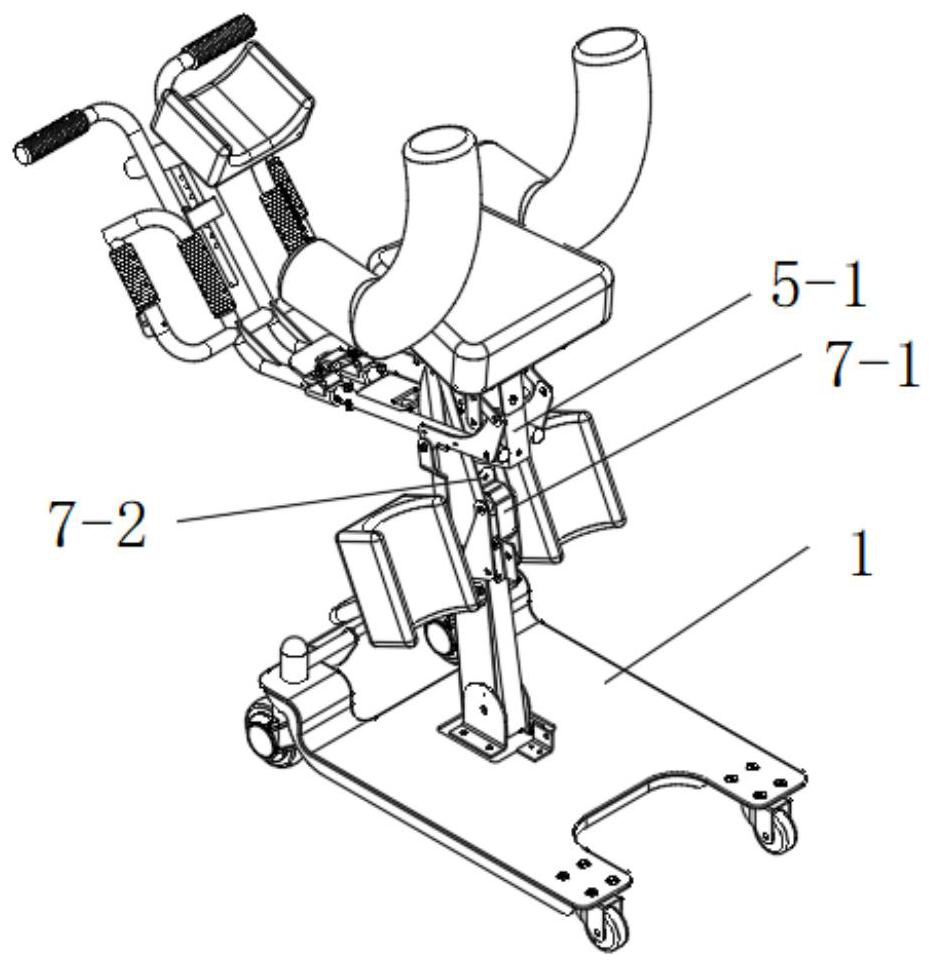
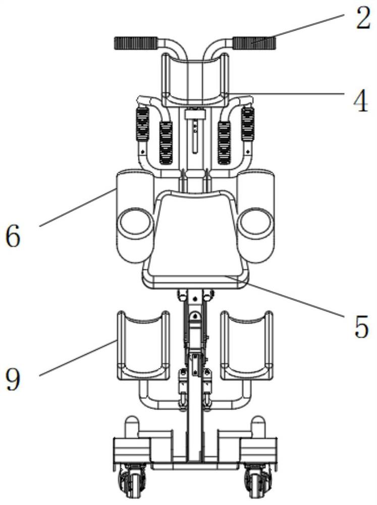
[0041] In an exemplary embodiment of the present invention, reference is made to Figure 1-Figure 9 As shown, a manual back lifter includes a base 1 and a support 8, the support 8 is installed on the base 1, the leg resting mechanism 9 is fixed on both sides, the support is inclined on the base, and the support mechanism 7 is installed It is arranged on one side of the support 8 and at a set angle with the support in the non-working state, and a buffer mechanism is arranged inside, wherein the support is U-shaped, the support mechanism is located on the opening side of the support, and the bottom end of the support mechanism 7 It is rotatably connected with the base 1 and can be rotated to the inside of the support. When the patient needs to be carried, the support mechanism is rotated to the inside of the opening of the support, and the support mechanism 7 is supported and limited by the support 8 to ensure that the lift is moving stability.

[0042] like Figure 4 and Im...


PUM


Abstract

The invention discloses a manual back type shifting machine, belongs to the technical field of medical equipment, solves the problems that in the prior art, a shifting machine can only meet the requirement for short-distance shifting of a patient, the requirement for a shifting site is high, and the shifting machine is seriously affected by spatial positions, and has the beneficial effects that the lifting function is achieved through the lever principle, and supporting of nursing personnel is omitted. According to the specific scheme, the manual back type shifting machine comprises a base, a moving mechanism is installed at the bottom of the base, a support is installed on the base, leg leaning mechanisms are fixed to the two sides of the base, a supporting mechanism is installed on one side of the support, a set angle is formed between the supporting mechanism and the support, and a buffering mechanism is arranged in the supporting mechanism. A first section of the lever mechanism is rotationally connected with the top of the supporting mechanism through a first connecting rod mechanism, one end of the first section supports the chest leaning mechanism, forking supporting mechanisms for supporting the oxters of a patient are installed on the two sides of the chest leaning mechanism, one end of a second section of the lever mechanism is rotationally connected with the first section, and the other end of the second section is bent and provided with a movable handle; a head protection mechanism is fixed to one side of the movable handle.

Description

technical field [0001] The invention relates to the technical field of medical equipment, in particular to a manual back-type lift. Background technique [0002] The statements in this section merely provide background information related to the present invention and do not necessarily constitute prior art. [0003] For disabled and paralyzed patients, nurses are required to assist in daily actions such as bathing, going to the toilet, getting out of bed, and lifting. These movements are heavy burdens for nursing staff. The lift is a short-distance assisted lift. The device, which is widely used for paralyzed, disabled, semi-disabled and other elderly people with disabilities, has become an indispensable part of the disabled person's assistive device industry. [0004] The existing seat lift has a single function and can only meet the needs of the nursing staff for short-distance lifting. For disabled people with limited mobility and patients with limited lower limbs, when...

Claims


Application Information

Patent Timeline
Patent Type & Authority Applications(China)
IPC IPC(8): A61G7/10A61G7/14
CPCA61G7/1013A61G7/1025A61G7/1046A61G7/1086
Inventor 凌腾程吕鹤婷王子洋赵斌姜军闫续范高镇冷基鑫
Owner CRRC SHANDONG CO LTD
Learn More