
Machine for automatically sucking liquid medicine

A liquid medicine and automatic technology, which can be applied to machines/engines, liquid variable volume machines, liquid fuel engines, etc., can solve the problems of inaccuracy, inconvenience in cutting ampoule, cumbersome and other problems, so as to improve practical effect, improve practicability and safety effect

Inactive Publication Date: 2022-07-08
恩施土家族苗族自治州中心医院
View PDF0 Cites 0 Cited by
  • Summary
  • Abstract
  • Description
  • Claims
  • Application Information

AI Technical Summary

Problems solved by technology

[0002] In the use of agriculture or medicine, it is necessary to pump the liquid medicine according to the requirements, so as to facilitate the operation of the user and improve the work efficiency. At present, the method of pumping the liquid medicine from the medicine tank or machine is realized by the dispensing equipment on the market. There are mainly two kinds, one is to use a peristaltic pump to suck, and the other is to use the principle of weighing to realize accurate suction, but the former is not accurate enough, and the latter is too complicated, so the present invention will be based on the existing improve the defects;
[0003] For example: it is not convenient to effectively cut the ampoule, it will cause the ampoule fragments to injure the staff, there is the possibility of contaminating the liquid medicine, the defect that the medicine liquid in the cilin ampoule is not easy to be exhausted, it is not convenient to effectively mix the medicine liquid , it is impossible to measure the remaining amount, it is difficult to carry out the suction operation, and the practical effect is not good. Therefore, we propose a machine for automatically suctioning the liquid medicine in order to solve the problems raised above

Method used


Image

  • Machine for automatically sucking liquid medicine
  • Machine for automatically sucking liquid medicine
  • Machine for automatically sucking liquid medicine

Examples


Embodiment Construction

[0037] The technical solutions in the embodiments of the present invention will be clearly and completely described below with reference to the accompanying drawings in the embodiments of the present invention. Obviously, the described embodiments are only a part of the embodiments of the present invention, but not all of the embodiments. Based on the embodiments of the present invention, all other embodiments obtained by those of ordinary skill in the art without creative efforts shall fall within the protection scope of the present invention.

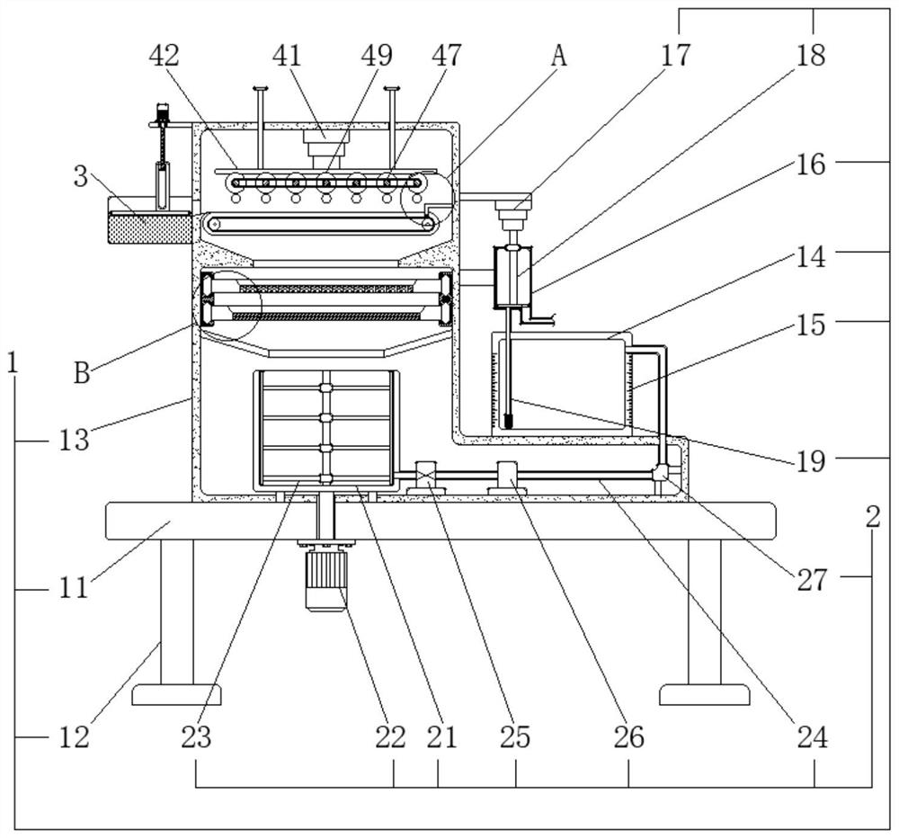
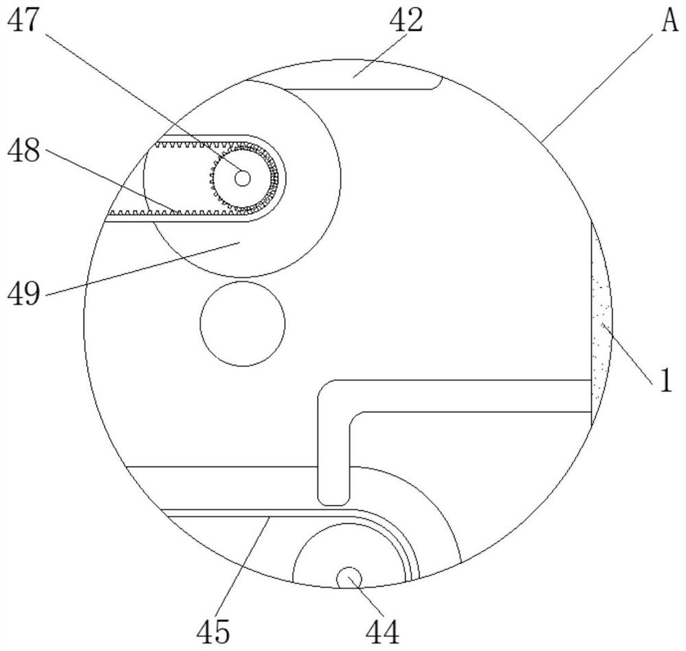
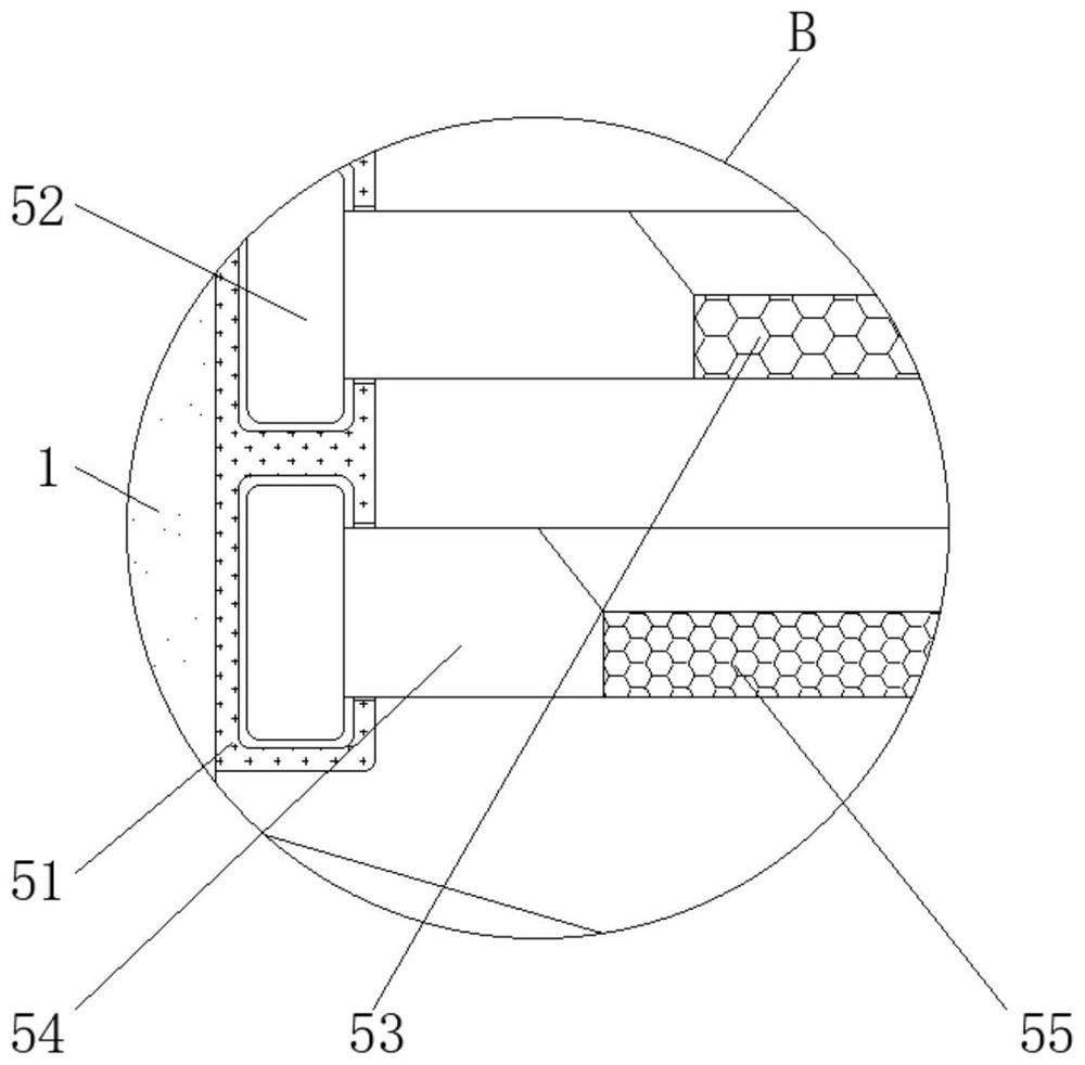
[0038] see Figure 1-7 , the present invention provides the following technical solutions: a machine for automatically suctioning medicinal liquid, comprising: a fixed assembly 1, a fixed installation base 11, a fixed leg 12, an outer frame body 13, a liquid storage tank 14, a scale line 15, a tubular box 16. The first electric telescopic rod 17, the piston rod 18, the filter connection pipe 19, the transmission assembly 2, the mixing...


PUM


Abstract

The invention discloses an automatic liquid medicine suction machine which comprises a fixing assembly, the fixing assembly further comprises a fixed mounting base, fixed supporting legs are mounted at the lower end of the fixed mounting base, a liquid storage tank is mounted on the upper right portion of an outer frame, a tubular box is arranged above scale marks, and a liquid medicine suction opening is formed in the tubular box. A first electric telescopic rod is arranged at the upper end of the piston rod; and the conveying assembly further comprises a mixing and stirring box, a first driving motor is arranged at the lower end of the mixing and stirring box, a communicating pipeline is arranged at the lower right end of the mixing and stirring box, and an infusion pump is arranged on the right side of an electric control valve. According to the machine for automatically sucking the liquid medicine, ampoule bottles can be effectively cut, the problems of injury to workers caused by ampoule fragments and safe injection are avoided, the liquid medicine can be effectively mixed and proportioned, then the remaining amount is measured, automatic suction operation is conveniently achieved, and the practical effect of the machine is improved.

Description

technical field [0001] The invention relates to the technical field of medicinal liquid, in particular to a machine for automatically suctioning medicinal liquid. Background technique [0002] In agricultural or medical use, it is necessary to suck the medicinal liquid according to the requirements, so as to facilitate the user's operation and improve the work efficiency. There are two main types, one is to use peristaltic pump suction, the other is to use the principle of weighing to achieve accurate suction, but the former is not accurate enough, and the latter is too cumbersome, so the present invention will be based on existing methods. bugs to improve; [0003] For example: it is inconvenient to cut the ampoule effectively, it will cause the ampoule fragments to hurt the staff, and it may contaminate the liquid medicine. , it is impossible to measure the remaining amount, it is difficult to perform the suction operation, and the practical effect is not good. Therefo...

Claims


Application Information

Patent Timeline
IPC IPC(8): F04B13/00F04B17/03F04B23/02F04B53/20B01F27/808B01F27/191B01F23/70
CPCF04B13/00F04B17/03F04B23/02F04B53/20Y02A50/30
Inventor 胡田婷左锐田华向登国田德黎李心雨
Owner 恩施土家族苗族自治州中心医院
Learn More