Display device and binding state detection method

A display device and binding technology, used in static indicators, instruments, nonlinear optics, etc., can solve the problems of incomplete separation of the drive circuit and the display panel, poor binding state, poor processing, etc., to ensure normal work and Reliability, improved efficiency, improved timeliness effects

Active Publication Date: 2022-07-05
MIANYANG HKC OPTOELECTRONICS TECH CO LTD +1
View PDF12 Cites 0 Cited by
  • Summary
  • Abstract
  • Description
  • Claims
  • Application Information

AI Technical Summary

Problems solved by technology

[0003] However, there may be poor processing during the binding process, and there may be poor binding status between the driving circuit and the display panel. For example, the driving circuit and the display panel are completely separated or not completely separated, and completely separated products Can't work normally, but the products that are not completely separated can still be displayed normally. With the prolongation of use time, the binding state will gradually deteriorate, and there will be a slight open circuit until it is completely separated, which will affect the reliability of the product during use.

Method used


Image

  • Display device and binding state detection method
  • Display device and binding state detection method
  • Display device and binding state detection method

Examples


Embodiment 1

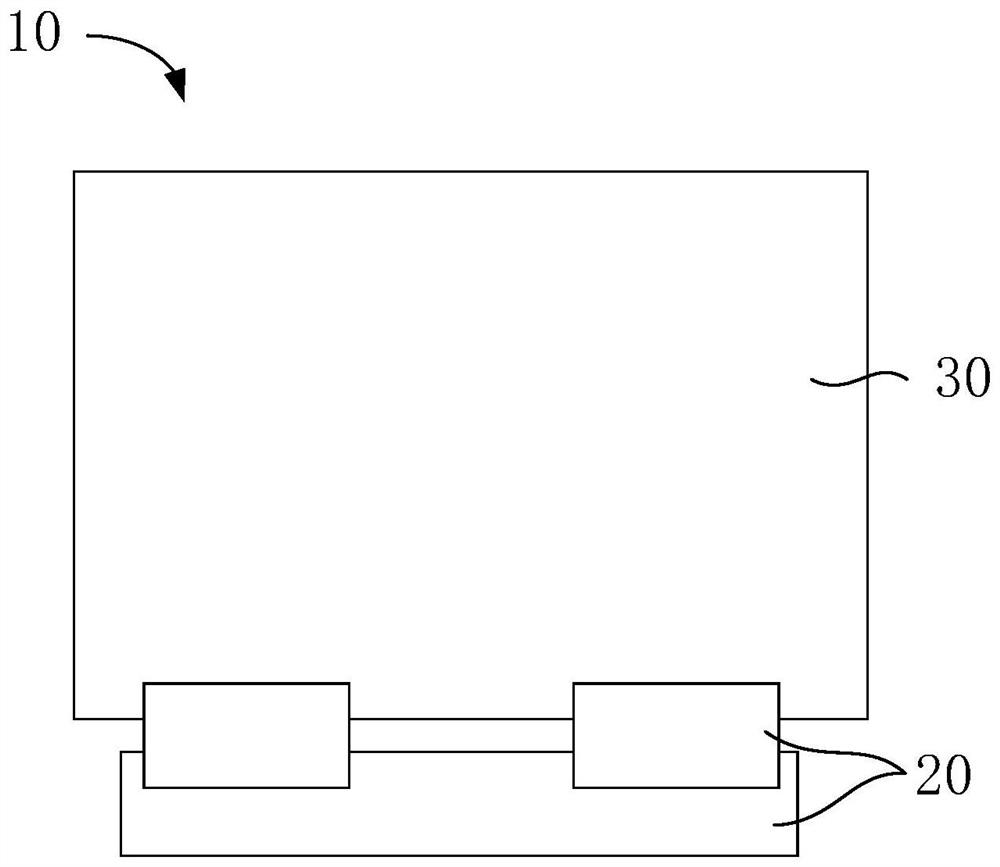
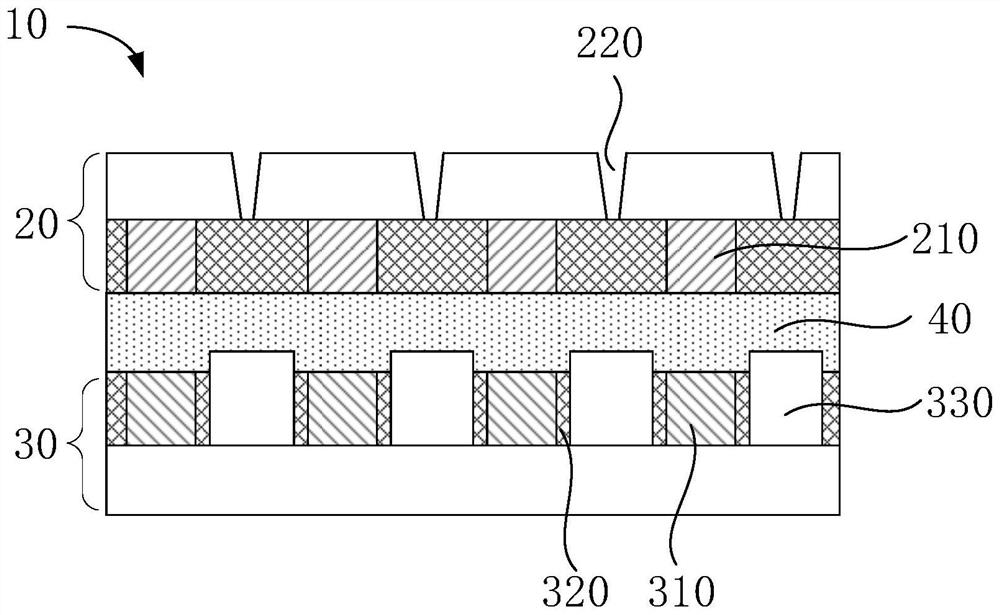
[0037] figure 1 is a schematic top view of a display device according to the first embodiment of the present application, figure 2 It is a schematic cross-sectional view of a display device according to the first embodiment of the present application, refer to figure 1 and figure 2It can be seen that, as the first embodiment of the present application, a display device 10 is disclosed, which includes a display panel 30 and a driving element 20 . The display panel 30 is bound and connected to the driving element 20 ; the driving element 20 includes a plurality of first binding terminals 210 , the display panel 30 includes a plurality of second binding terminals 310, the first binding terminals 210 are connected to the second binding terminals 310 through the anisotropic conductive adhesive 40 in a one-to-one correspondence, the display panel 30 further includes a force-sensitive material layer 330, There are at least two force-sensitive material layers 330 , the force-sensi...

Embodiment 2

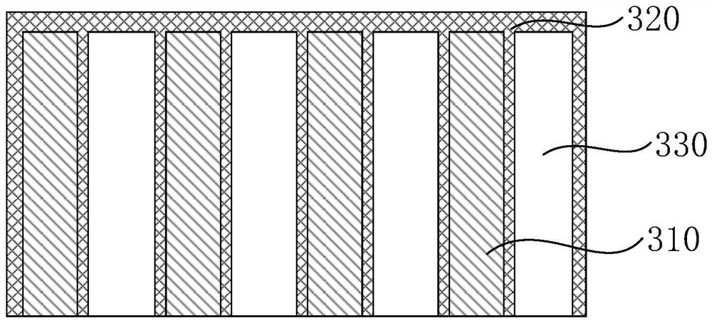
[0056] Figure 5 It is a schematic top view of the display panel in the second embodiment of the present application, refer to Figure 5 It can be seen that, different from the first embodiment, each force-sensitive material layer 330 is arranged in sections along the length direction of the first binding terminal 210 or the second binding terminal 310 .

[0057] In this embodiment, the force-sensitive material layer 330 and the second binding terminal 310 are alternately arranged at intervals as an example. Each force-sensitive material layer 330 is arranged in sections along the length direction of the second binding terminal 310 . It includes a plurality of force-sensitive material blocks 333, and the plurality of force-sensitive material blocks 333 are arranged at intervals, arranged along the length direction of the second binding terminals 310, and arranged between two adjacent second binding terminals 310, The force-sensitive material block 333 converts the force in di...


PUM


Abstract

The invention discloses a display device and a binding state detection method, the display device comprises a display panel and a driving element, and the display panel is in binding connection with the driving element; the display panel further comprises at least two force-sensitive material layers, the force-sensitive material layers and the first binding terminals or the second binding terminals are arranged in a staggered mode at intervals, and each force-sensitive material layer is insulated from the adjacent first binding terminal or second binding terminal. The force-sensitive material layer is used for detecting the binding state between the display panel and the driving element, when the binding state between the display panel and the driving element is normal, the force-sensitive material layer is in a compressed state, and when the force-sensitive material layer is pressed to deform, the force-sensitive material layer sends out an electric signal. In this way, the binding state between the display panel and the driving element is judged by detecting the electric signal sent by the force-sensitive material layer, and normal work and reliability of a product are guaranteed.

Description

technical field [0001] The present application relates to the field of display technology, and in particular, to a display device and a method for detecting a binding state. Background technique [0002] A display device usually includes a display panel and a drive circuit. During the production process, the drive circuit is usually fixed on the display panel by means of binding. Specifically, the adhesiveness of anisotropic conductive adhesive is used to bind the drive circuit to the display panel. The display panel is further connected to the drive circuit and the circuit in the display panel. [0003] However, there may be poor processing during the bonding process, and the bonding state between the driving circuit and the display panel may be poor. For example, the driving circuit and the display panel may be completely separated or not completely separated, while the completely separated product Products that cannot work properly but are not completely separated can st...

Claims


Application Information

Patent Timeline
Patent Type & Authority Applications(China)
IPC IPC(8): G02F1/13G09G3/00
CPCG02F1/1309G09G3/006
Inventor 张建英康报虹
Owner MIANYANG HKC OPTOELECTRONICS TECH CO LTD
Why Eureka
Try Eureka