Pulse width monitoring protection circuit

A technology for monitoring and protecting circuits and pulse widths, applied in pulse description, electrical components, AC motor control, etc., can solve problems such as abnormal excitation signals, pulse width changes, damage, etc., and achieve the effect of avoiding the reduction of reliability

Pending Publication Date: 2022-03-01
SUZHOU R&D CENT OF NO 214 RES INST OF CHINA NORTH IND GRP
View PDF0 Cites 0 Cited by
  • Summary
  • Abstract
  • Description
  • Claims
  • Application Information

AI Technical Summary

Problems solved by technology

During the aging process, the output signal of the excitation signal source is often unstable, the pulse width changes, or the excitation source fails, causing the excitation signal to become a fixed high level or low level.
These changes can lead to increased power consumption of products that are stimulated and aged, greatly reducing product life, or directly damaging
Especially for power circuits with large power consumption during operation, abnormal excitation signals can easily lead to rapid heat generation and damage to the product

Method used


Image

  • Pulse width monitoring protection circuit
  • Pulse width monitoring protection circuit
  • Pulse width monitoring protection circuit

Examples


Embodiment 1

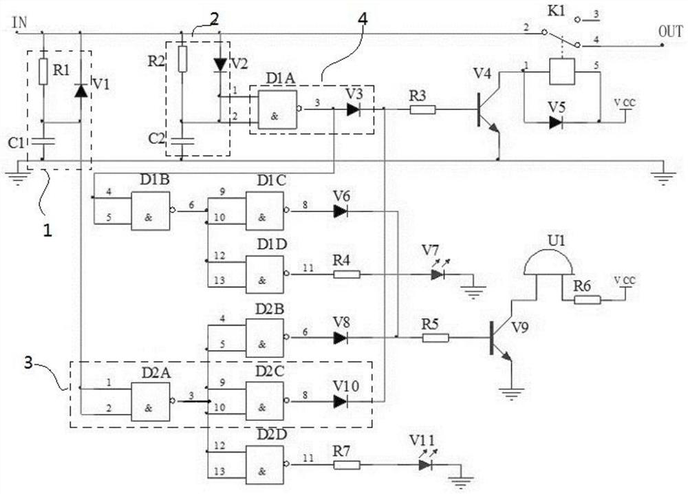
[0037] The pulse width monitoring and protection circuit of this embodiment is as follows: figure 1 As shown, it includes a pulse high-level width monitoring unit, a pulse low-level width monitoring unit, and a protection output unit; the pulse high-level width monitoring unit includes a first signal conversion circuit and a first logic judgment circuit, and pulse low-level width monitoring The unit includes a second signal conversion circuit and a second logic judgment circuit. The protection output unit includes a relay. The relay coil is connected to the VCC power circuit through a controllable switch. The normally closed contacts of the relay are connected in series to the signal transmission line of the pulse signal to be detected. , The controllable switch V4 adopts a triode.

[0038] In the pulse high level width monitoring unit, the first signal conversion circuit 1 includes a resistor R1 and a capacitor C1 connected in series between the signal transmission line and t...


PUM


Abstract

The invention discloses a pulse width monitoring protection circuit which comprises a pulse high-level width monitoring unit, a pulse low-level width monitoring unit and a protection output unit. In the protection output unit, a relay coil is connected in a power supply loop through a controllable switch, and a relay normally-closed contact is connected in series in a signal transmission line of a pulse signal to be detected; the pulse high-level width monitoring unit converts the pulse high-level width of the detected pulse signal into a voltage signal to be output, and outputs a controllable switch driving signal according to the voltage signal; the pulse low-level width monitoring unit is used for converting the pulse low-level width into a voltage signal and outputting the voltage signal, and outputting a controllable switch driving signal according to the voltage signal; when the pulse high level width or the pulse low level width is out of the preset range, the controllable switch is switched on, and the relay normally-closed contact disconnects the signal transmission line. According to the invention, pulse width monitoring can be carried out on the pulse signal for aging excitation, signal transmission is blocked when the pulse signal is abnormal, and the situation that the reliability of the excited circuit is reduced or damaged due to the abnormal pulse signal is avoided.

Description

technical field [0001] The invention relates to the technical field of electronic circuits, in particular to a pulse width monitoring and protection circuit. Background technique [0002] In the development and production process of integrated circuits, it is often necessary to apply pulse signals to the integrated circuits for burn-in stimulation. During the burn-in process, the output signal of the excitation signal source is often unstable, the pulse width changes, or the excitation source fails, causing the excitation signal to become a fixed high level or low level. These changes can lead to increased power consumption of energized and aged products, greatly reduced product life, or outright damage. Especially for power circuits with large power consumption during operation, abnormal excitation signals can easily lead to rapid heat generation and damage to the product. Contents of the invention [0003] The purpose of the present invention is to provide a pulse widt...

Claims


Application Information

Patent Timeline
IPC IPC(8): H02P27/08H02M7/48H03K5/125
CPCH02P27/08H02M7/48H03K5/125
Inventor 高加林王海建杨翠侠王国宁
Owner SUZHOU R&D CENT OF NO 214 RES INST OF CHINA NORTH IND GRP
Why Eureka
Try Eureka