Improved Miller type expansion joint device and mounting method thereof
An installation method and expansion joint technology, applied in the field of bridge engineering, can solve the problems of increased maintenance costs, long construction period, shortened service life of bridges, etc., and achieve the effects of improving construction quality, high tensile strength, and simplifying construction
- Summary
- Abstract
- Description
- Claims
- Application Information
AI Technical Summary
Problems solved by technology
Method used
Image


Examples
Embodiment 1
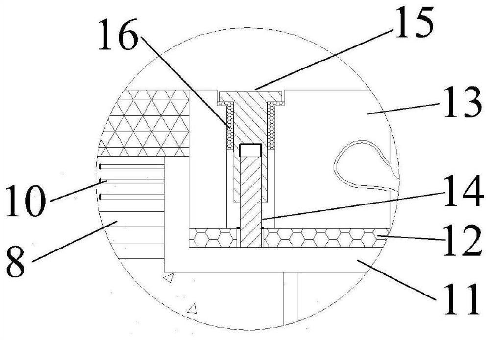
[0057] The bridge in this embodiment is a multi-span simply supported girder bridge, the main girder is a concrete box girder, and the width of the expansion joint is 60 mm. figure 1 It is a schematic cross-sectional view of the expansion joint device after installation, figure 2 for figure 1 In the partial enlarged schematic diagram of part A in the middle, there is a reserved groove at the end of the beam body 1, and there are door-shaped steel bars 6 extending upwards. The door-shaped steel bars 6 are ribbed steel bars with a diameter of 16 mm. The improved Maurer-type expansion joint device is symmetrically arranged with respect to the expansion joint, and includes an upper subsection, a lower subsection, a rubber backing plate 12 between the two subsections, and an anchoring concrete connecting the lower subsection and the beam body 1 as a whole. 2. The anchor concrete 2 is high-toughness concrete mixed with steel fibers 25 . The lower subassembly in contact with the ...
Embodiment 2
[0077] The bridge of this embodiment was installed with the expansion joint device of the present invention several years ago. Since the asphalt layer 4 is damaged, it is now decided to lay a new asphalt overlay 21 on the original asphalt layer 4. See Figure 10 . The specific construction steps are as follows:
[0078] Step 1: Unscrew the connector 15, remove the special-shaped steel rod 13 and the rubber pad 12 below, and place the stitch pad 20. The upper surface of the stitch pad 20 is flush with the upper surface of the existing asphalt layer 4;
[0079] Step 2 The entire line is paved with an asphalt overlay 21;
[0080] Step 3: Cut off the upper asphalt overlay 21 corresponding to the horizontal plate of the L-shaped steel plate 11, take out the seam backing plate 20, and clean the L-shaped steel plate 11;
[0081] Step 4 Considering that the original rubber backing plate 12 is in good condition, it is decided to reuse it and place the newly added rubber height-adjust...
Embodiment 3
[0084] This embodiment is a modification of Embodiment 1, see Figure 11 . In this embodiment, the structure of the expansion joint device is slightly improved in order to prevent and avoid the large slippage of the special-shaped steel rod 13 due to excessive horizontal force. On the horizontal plate of the L-shaped steel plate 11 , there are protruding strips 23 along the longitudinal direction of the expansion joint, and at the same time, the bottom of the special-shaped steel rod 13 has a corresponding groove 24 . A rubber backing plate 12 with an initial thickness of 10mm is installed between the L-shaped steel plate 11 and the special-shaped steel rod 13. The left end of the rubber backing plate 12 is bent upwards and is close to the side of the special-shaped steel rod 13 close to the asphalt layer 4. The upper surface of layer 4 is of equal height. The rubber backing plate 12 adopts a water-stop rubber belt. In addition, add 0.2% expansion agent to the fiber concret...
PUM
 Abstract
Description
Claims
Application Information
 - Generate Ideas
- Intellectual Property
- Life Sciences
- Materials
- Tech Scout
- Unparalleled Data Quality
- Higher Quality Content
- 60% Fewer Hallucinations
Browse by: Latest US Patents, China's latest patents, Technical Efficacy Thesaurus, Application Domain, Technology Topic, Popular Technical Reports.
© 2025 PatSnap. All rights reserved.Legal|Privacy policy|Modern Slavery Act Transparency Statement|Sitemap|About US| Contact US: help@patsnap.com