


Quick Research
Generate reliable direction feasibility study reports for your R&D in just a few steps.

Technical Q&A
Discover and master advanced knowledge NOW. Basics, ideas, possibilities, all at once.

Find Solutions
As an expert in R&D theories, this can generate solutions to your technical problems instantly.

Evaluate Feasibility
Analyze your overall solution with one click, know your potential R&D risks in advance.

Monitor Landscape
Get weekly tech updates, stay abreast of the latest tech innovations and key insights.
Radial positioning code disc
A radial positioning and code disc technology, applied in the direction of manufacturing tools, workpiece clamping devices, etc., can solve the problems of radial overstress protection, the inability to achieve precise positioning at any radial position, etc., achieve rapid positioning and improve assemblability and the effect of maintainability
- Summary
- Abstract
- Description
- Claims
- Application Information
AI Technical Summary
Problems solved by technology
Method used
Image

Examples
Embodiment 1
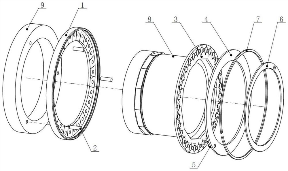
[0043] Example 1, see Figure 1-6 ,like figure 1 As shown, in this embodiment, a radial positioning code wheel includes:
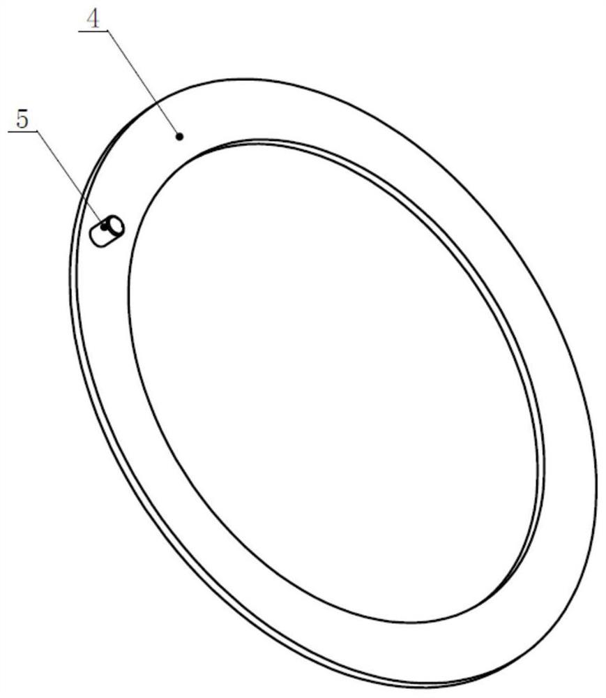
[0044] Reference plate 1, floating plate 3, fixed ring 4, retaining ring 6, retaining ring 7, outer sleeve 9 and inner sleeve 8;
[0045] The reference disk 1 and the outer sleeve 9 are fixed to rotate as a whole, and the reference disk 1 is fixed on the end face of the outer sleeve 9;
[0046] The floating disk 3 and the inner sleeve 8 are fixed to rotate as a whole, and the floating disk 3 is fixed to the outer wall surface of the inner sleeve 8;
[0047] The inner sleeve 8 and the outer sleeve 9 are inserted and matched, and the inner sleeve 8 and the outer sleeve 9 can rotate with each other;
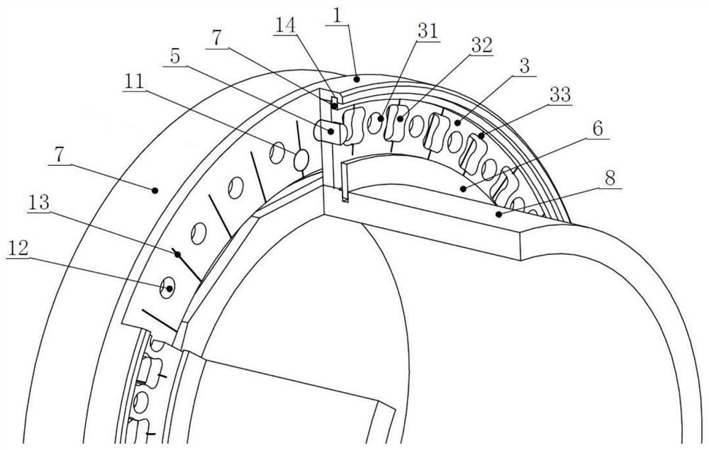
[0048] The reference disk 1 and the floating disk 3 are stacked and slidably matched; the reference disk 1 has n first holes 12, and the n holes are uniformly distributed in a ring shape, and the radius of the ring distribution circle is r; the floating disk ...
Embodiment 2
[0052] Example 2, see Figure 1-7 ,like figure 1 As shown, in this embodiment, a radial positioning code wheel includes:
[0053] Reference plate 1, floating plate 3, fixed ring 4, retaining ring 6, retaining ring 7, outer sleeve 9 and inner sleeve 8;
[0054] The reference disk 1 and the outer sleeve 9 are fixed to rotate as a whole, and the reference disk 1 is fixed on the end face of the outer sleeve 9;
[0055] The floating disk 3 and the inner sleeve 8 are fixed to rotate as a whole, and the floating disk 3 is fixed to the outer wall surface of the inner sleeve 8;
[0056] The inner sleeve 8 and the outer sleeve 9 are inserted and matched, and the inner sleeve 8 and the outer sleeve 9 can rotate with each other;
[0057] The reference disk 1 and the floating disk 3 are stacked and slidably matched; the reference disk 1 has n first holes 12, and the n holes are uniformly distributed in a ring shape, and the radius of the ring distribution circle is r; the floating disk ...
Embodiment 3
[0062] Example 3, see Figure 1-6 ,like figure 1 As shown, in this embodiment, a radial positioning code wheel includes:
[0063] Reference plate 1, floating plate 3, fixed ring 4, retaining ring 6, retaining ring 7, outer sleeve 9 and inner sleeve 8;
[0064] The reference disk 1 and the outer sleeve 9 are fixed to rotate as a whole, and the reference disk 1 is fixed on the end face of the outer sleeve 9;
[0065] The floating disk 3 and the inner sleeve 8 are fixed to rotate as a whole, and the floating disk 3 is fixed to the outer wall surface of the inner sleeve 8;
[0066] The inner sleeve 8 and the outer sleeve 9 are inserted and matched, and the inner sleeve 8 and the outer sleeve 9 can rotate with each other;
[0067] The reference disk 1 and the floating disk 3 are stacked and slidably matched; the reference disk 1 has n first holes 12, and the n holes are uniformly distributed in a ring shape, and the radius of the ring distribution circle is r; the floating disk ...
PUM
 Abstract
Description
Claims
Application Information
 - R&D Engineer
- R&D Manager
- IP Professional
- Industry Leading Data Capabilities
- Powerful AI technology
- Patent DNA Extraction
Browse by: Latest US Patents, China's latest patents, Technical Efficacy Thesaurus, Application Domain, Technology Topic, Popular Technical Reports.
© 2024 PatSnap. All rights reserved.Legal|Privacy policy|Modern Slavery Act Transparency Statement|Sitemap|About US| Contact US: help@patsnap.com