
Non-contact connector

A non-contact, connector technology, applied in the direction of contact parts, optical waveguide coupling, etc., can solve the problems of fiber end face damage, ferrule end face unevenness, contact end face wear, etc., to solve the problem of ferrule easy to wear. Effect

Pending Publication Date: 2022-07-01
ANHUI LANXUAN PHOTOELECTRIC TECH CO LTD
View PDF0 Cites 0 Cited by
  • Summary
  • Abstract
  • Description
  • Claims
  • Application Information

AI Technical Summary

Problems solved by technology

[0002] The traditional connector is usually a contact connector, that is, the end faces of the two ferrules need to be in contact when the signal is transmitted. When the connector is working normally, the ferrule will rotate relative to each other, thereby causing wear on the contacting end faces. After a period of use, it will The end face of the ferrule is uneven, the end face of the optical fiber is damaged, and the transmission loss of the optical signal is increased, and the signal cannot be transmitted normally.

Method used


Image

  • Non-contact connector
  • Non-contact connector
  • Non-contact connector

Examples


Embodiment Construction

[0024] In order to make the objects and advantages of the present invention more clear, the present invention will be specifically described below with reference to the embodiments. It should be understood that the following text is only used to describe one or more specific embodiments of the present invention, and does not strictly limit the protection scope of the specific claims of the present invention. The existing structures that are not described in detail in the present invention are all implemented according to the existing technical solutions.

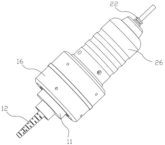
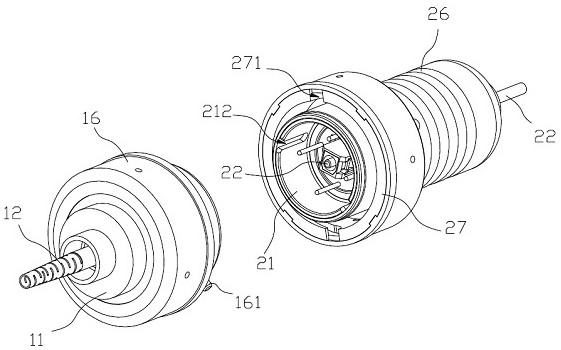
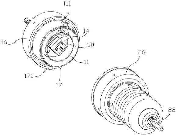
[0025] like figure 1 , 2 As shown in , 3, a non-contact connector includes first and second housings arranged opposite to each other, the first housing is provided with a first mounting assembly for rotatably assembling the first connector 12 in the first housing; The second housing is provided with a second mounting assembly for the second connector 22 to be rotatably assembled in the second housing, the first connector 1...


PUM


Abstract

The non-contact type connector comprises a first shell and a second shell which are oppositely arranged, a first installation assembly used for assembling a first connector in the first shell in a rotating mode is arranged in the first shell, and a second installation assembly used for assembling a second connector in the second shell in a rotating mode is arranged in the second shell. A first inserting core is arranged in the first connector, a second inserting core is arranged in the second connector, a connecting assembly is arranged between the first connector and the second connector, the connecting assembly is used for enabling the first inserting core and the second inserting core to be oppositely arranged at intervals and enabling the first connector and the second connector to rotate synchronously, and a fixing assembly used for achieving detachable fixed connection of the first shell and the second shell is arranged between the first shell and the second shell. According to the scheme, the first insertion core and the second insertion core are arranged in a non-contact mode and rotationally installed, and therefore the problem that the insertion cores in a traditional connector are prone to abrasion is solved.

Description

technical field [0001] The present invention relates to a contactless connector. Background technique [0002] Traditional connectors are usually contact connectors, that is, the end faces of the two ferrules need to be in contact during signal transmission. When the connector is working normally, the ferrules will rotate relative to each other, resulting in wear on the contacted end faces, which will be damaged after a period of use. The end face of the ferrule is uneven, and the end face of the optical fiber is damaged, causing the transmission loss of the optical signal to increase, and the signal cannot be transmitted normally. SUMMARY OF THE INVENTION [0003] In order to solve the above problems, the present invention provides a contactless connector. [0004] The technical solutions adopted in the present invention are as follows. [0005] A non-contact connector is characterized in that it comprises first and second housings arranged oppositely, the first housing...

Claims


Application Information

Patent Timeline
Patent Type & Authority Applications(China)
IPC IPC(8): G02B6/38H01R13/02
CPCG02B6/3817G02B6/3873H01R13/02
Inventor 张录娟
Owner ANHUI LANXUAN PHOTOELECTRIC TECH CO LTD
Learn More