
Transfer mechanism and transfer equipment

A technology of transferring and sliding parts, which is applied to conveyors, conveyor objects, transportation and packaging, etc., can solve the problems that the manipulator is not suitable for transferring multiple materials, the utilization rate of turntable space is low, and the conveyor belt is uncomfortable. High speed, simple structure and stable operation

Pending Publication Date: 2022-07-01
厦门威芯泰科技有限公司
View PDF0 Cites 0 Cited by
  • Summary
  • Abstract
  • Description
  • Claims
  • Application Information

AI Technical Summary

Problems solved by technology

[0003] The purpose of the present invention is to overcome the problems in the background technology that the conveyor belt is not suitable for step-by-step transfer of small materials, the space utilization rate of the turntable is low and the price is high, and the manipulator is not suitable for transferring multiple materials. Loading mechanism and transfer equipment

Method used


Image

  • Transfer mechanism and transfer equipment
  • Transfer mechanism and transfer equipment
  • Transfer mechanism and transfer equipment

Examples


Embodiment 1

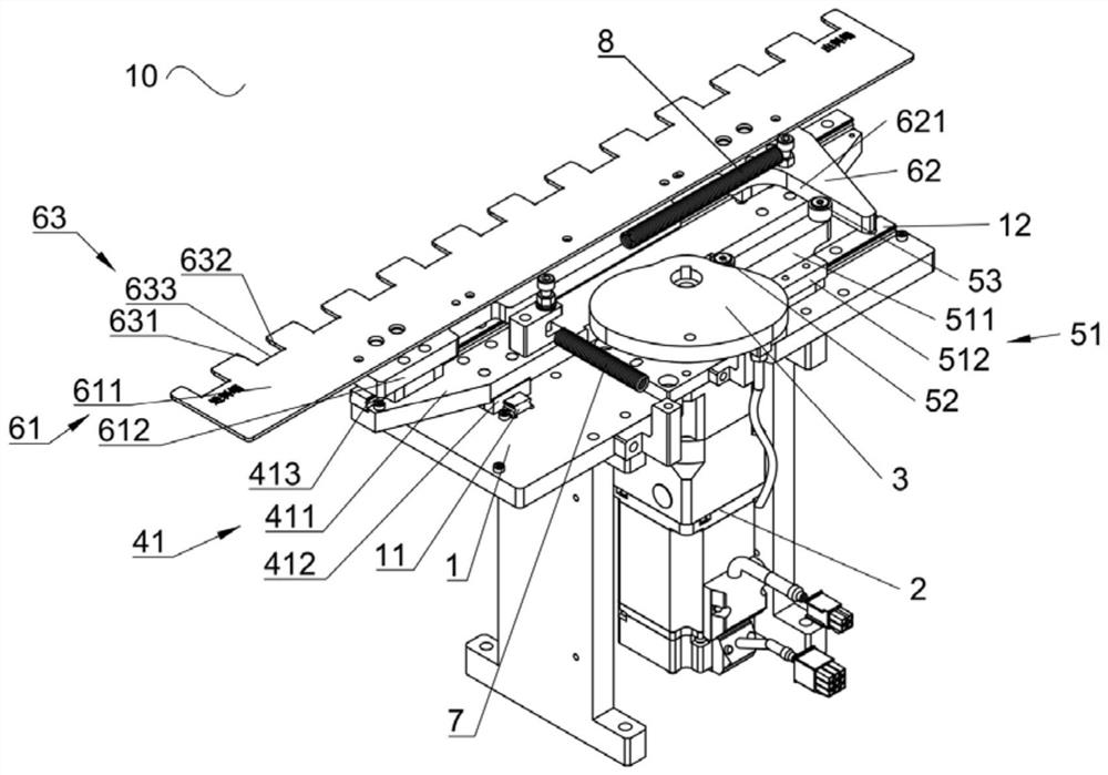
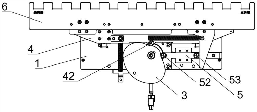
[0050] refer to figure 1 , figure 2 , a transfer mechanism 10, which is used to transfer materials, the transfer mechanism 10 includes a base 1, a rotary drive member 2, a rotary member 3, a first sliding member 4, a second sliding member 5, a transfer member 6, The first reset member 7 and the second reset member 8.

[0051] Base 1, the base 1 is provided with two first slide rails 11 extending along the first direction and a second slide rail 12 extending along the second direction;

[0052] When the driving member 2 is rotated, the output end of the rotary driving member 2 rotates around the first axis, and the first axis, the first direction and the second direction are perpendicular to each other. Specifically, the rotating driving member 2 is a servo motor, and the transmission is stable. The casing of the servo motor is fixed on the base 1 for stable installation.

[0053] The rotating member 3 is fixedly connected with the output shaft of the rotating driving memb...

Embodiment 2

[0070] refer to Figure 5 , a transfer device, comprising a carrier 20 and the above-mentioned transfer mechanism 10, the carrier 20 extends along the second direction and is used to carry materials to assist the transfer mechanism 10 to transfer the materials, and the carrier 20 is provided with The chute 201 extends along the second direction. The chute 201 opens upward and is suitable for the material to extend so that the material can be transferred by the transfer mechanism 10. The bottom wall of the chute 201 forms a bearing surface. When the material is placed in the chute 201, the movement of the material in the first direction is restricted to prevent the material from running. Further, the chute 201 and the limiting surface 632 cooperate together to determine the stepping distance of the material during the movement process, and it will not be easily Offset to achieve precise positioning, which is convenient for the next detection or processing of materials.

[0071...


PUM


Abstract

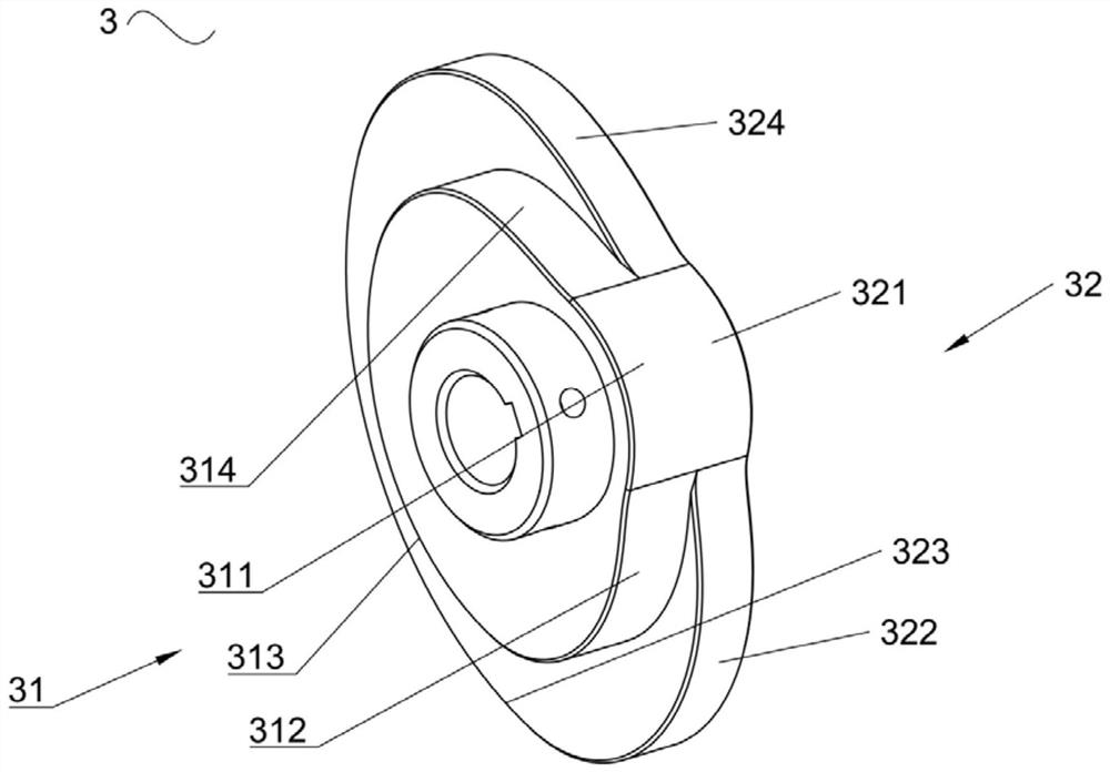
The invention discloses a transferring mechanism and transferring equipment. The transferring mechanism comprises a base, a rotating piece, a first sliding piece, a second sliding piece, a transferring piece, a first reset piece and a second reset piece. The rotating part comprises a first cam and a second cam, when the rotating part rotates, the first cam drives the transferring part to move in the first direction through the first sliding part, and the second cam drives the transferring part to move in the second direction through the second sliding part. And under the action of the first reset piece and the second reset piece, the transferring piece is reset to the initial position after moving, and transferring of the materials in the second direction is achieved through circulation of the actions. The transferring mechanism is high in transferring speed, stable in operation, simple in structure, low in cost, convenient to install and maintain, small in working range and suitable for transferring a plurality of light and small materials.

Description

technical field [0001] The invention relates to the field of relay equipment, in particular to a transfer mechanism and transfer equipment. Background technique [0002] The transfer mechanism is used to transfer materials. Commonly used transfer mechanisms include conveyor belts, manipulators, turntables, etc. The conveyor belt is not suitable for step-by-step transfer of small materials, such as relays. When the conveyor belt is suspended, the relay will still move forward due to inertia. Slippage affects the follow-up; the turntable transports materials by rotating, but the space utilization rate is low and the price is high; the manipulator is easy to use, but when multiple materials are transported synchronously, multiple manipulators are needed, and the adjacent manipulators are Prevent the interference distance from increasing. For small materials, the length of the transportation line is greatly increased, which is inconvenient to use, difficult to install, and high ...

Claims


Application Information

Patent Timeline
IPC IPC(8): B65G47/82B65G25/02B65G47/22
CPCB65G47/82B65G25/02B65G47/22
Inventor 胡金龙汪长瑞马梓万朱朝军张建城王磊
Owner 厦门威芯泰科技有限公司
Learn More