
Vacuum servo assistance system, vehicle control method, storage medium and vehicle

A vacuum servo and booster system technology, applied in the field of vehicles, can solve problems such as poor braking effect of vehicles, potential safety hazards of vehicles, and failure of vacuum boosters to reach the highest vacuum degree, so as to reduce potential safety hazards, increase boosting effect, and improve control effect of animation

Active Publication Date: 2022-07-01
BEIQI FOTON MOTOR CO LTD
View PDF8 Cites 0 Cited by
  • Summary
  • Abstract
  • Description
  • Claims
  • Application Information

AI Technical Summary

Problems solved by technology

[0003] However, after the vehicle is equipped with a vacuum tank, the electric vacuum pump pumps the air in the vacuum booster assembly and the vacuum tank, so that the time for the vacuum booster assembly to reach the highest vacuum degree increases. The vacuum booster may not be able to reach the highest vacuum level during the second braking, resulting in poor braking effect of the vehicle, which poses a greater safety hazard to the vehicle

Method used


Image

  • Vacuum servo assistance system, vehicle control method, storage medium and vehicle
  • Vacuum servo assistance system, vehicle control method, storage medium and vehicle
  • Vacuum servo assistance system, vehicle control method, storage medium and vehicle

Examples


Embodiment Construction

[0030] The specific embodiments of the present disclosure will be described in detail below with reference to the accompanying drawings. It should be understood that the specific embodiments described herein are only used to illustrate and explain the present disclosure, but not to limit the present disclosure.

[0031] In the following description, words such as "first" and "second" are only used for the purpose of distinguishing descriptions, and cannot be understood as indicating or implying relative importance, nor can they be understood as indicating or implying order.

[0032] First, the application scenarios of the present disclosure will be described. The present disclosure can be applied to vehicles using a vacuum servo booster system. Currently, electric vacuum pumps are used as vacuum sources for new energy electric vehicles to extract air from the vacuum booster assembly, and some models will add a vacuum tank as a vacuum reserve. When the driver brakes in an emer...


PUM


Abstract

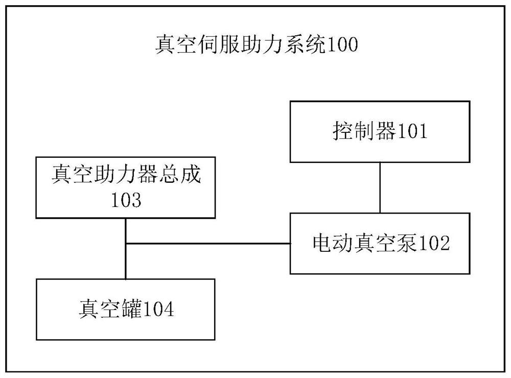
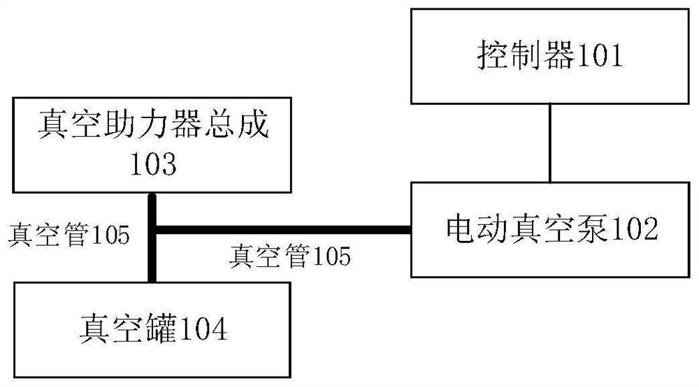
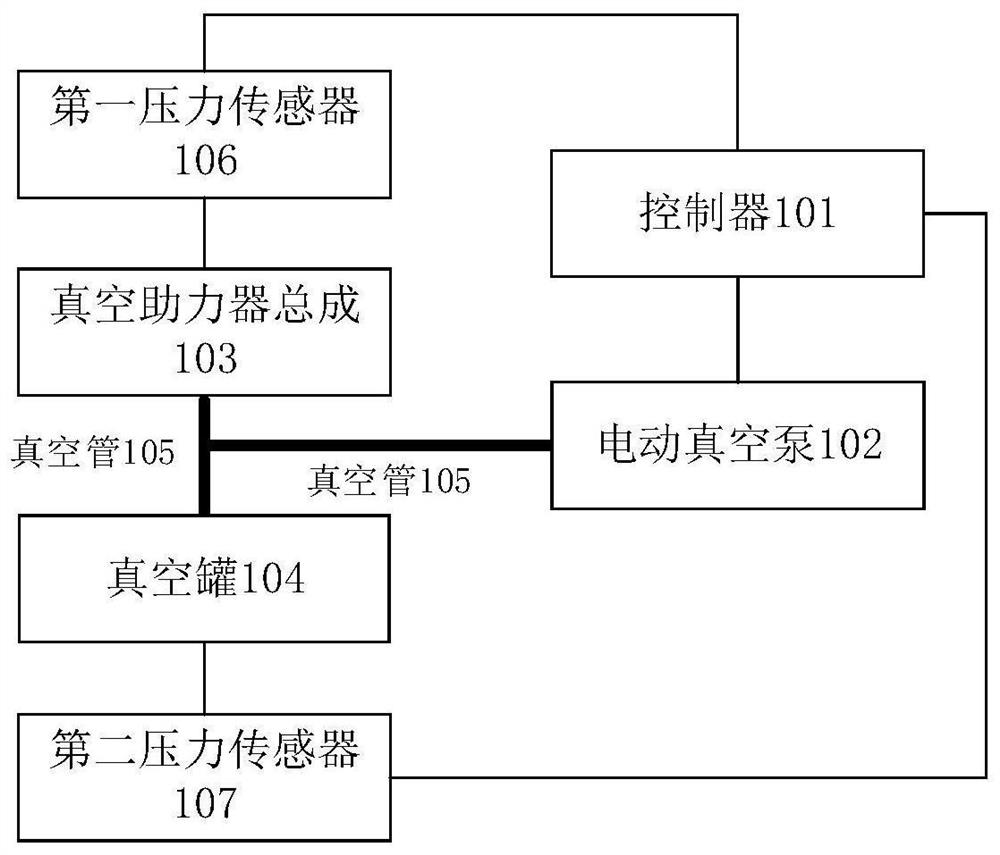
The invention relates to a vacuum servo boosting system, a vehicle control method, a storage medium and a vehicle. The system comprises a controller, an electric vacuum pump, a vacuum booster assembly and a vacuum tank. The controller is connected with the electric vacuum pump, the vacuum booster assembly is connected with the vacuum tank, and the electric vacuum pump is respectively connected with the vacuum booster assembly and the vacuum tank; the controller is used for controlling the electric vacuum pump to extract air in the vacuum booster assembly under the condition that the vacuum pressure of the vacuum booster assembly is smaller than or equal to a preset minimum pressure threshold value, and controlling the electric vacuum pump to extract air in the vacuum booster assembly under the condition that the first real-time vacuum pressure of the vacuum booster assembly reaches a preset maximum pressure threshold value. And when the second real-time vacuum pressure in the vacuum tank reaches the preset maximum pressure threshold value, the electric vacuum pump is controlled to extract air in the vacuum tank, and when the second real-time vacuum pressure in the vacuum tank reaches the preset maximum pressure threshold value, the electric vacuum pump is controlled to stop extracting the air in the vacuum tank. In this way, the braking effect of the vehicle can be improved, and potential safety hazards of the vehicle are reduced.

Description

technical field [0001] The present disclosure relates to the technical field of vehicles, and in particular, to a vacuum servo booster system, a vehicle control method, a storage medium, and a vehicle. Background technique [0002] At present, new energy electric vehicles all use electric vacuum pumps as vacuum sources, and some models will add vacuum tanks as vacuum reserves. When the driver brakes in an emergency, the vacuum is consumed, and when the vacuum level drops to the working threshold, the electric vacuum pump starts to work to vacuumize. [0003] However, after the vacuum tank is added to the vehicle, the electric vacuum pump draws the air in the vacuum booster assembly and the vacuum tank, so that the time for the vacuum booster assembly to reach the highest vacuum level increases. During the first braking, the vacuum booster may not reach the maximum vacuum level, resulting in poor braking effect of the vehicle and a greater safety hazard for the vehicle. SU...

Claims


Application Information

Patent Timeline
Patent Type & Authority Applications(China)
IPC IPC(8): B60T13/52B60T13/72
CPCB60T13/52B60T13/72
Inventor 徐磊
Owner BEIQI FOTON MOTOR CO LTD
Learn More