
Industrial environmental protection equipment for biological pollutants

A technology for environmental protection equipment and pollutants, which is applied in separation methods, dispersed particle separation, chemical instruments and methods, etc., can solve the problems of cumbersome installation and removal of filter screens, increasing the work intensity of staff, and inability to adjust the angle of the suction device, etc. To achieve the effect of simplifying disassembly and installation, enhancing practicability, and facilitating cleaning

Pending Publication Date: 2022-07-01
山东高洁环保科技有限公司
View PDF0 Cites 0 Cited by
  • Summary
  • Abstract
  • Description
  • Claims
  • Application Information

AI Technical Summary

Problems solved by technology

[0006] The purpose of the present invention is to address the deficiencies of the prior art, to provide an industrial environmental protection equipment for biological pollutants, to solve the problem that the internal filter screen will be damaged after a period of time when the existing environmental protection equipment proposed in the background technology is in use. , the dust needs to be cleaned, but the installation and removal of the filter is cumbersome, which increases the work intensity of the staff and reduces the work efficiency. Moreover, when the existing environmental protection equipment is in use, it is difficult to collect the dust inside the environmental protection equipment. Large, and the angle of the suction device cannot be adjusted, and the suction direction can only be adjusted by moving the main body of the device, which is not very practical

Method used


Image

  • Industrial environmental protection equipment for biological pollutants
  • Industrial environmental protection equipment for biological pollutants
  • Industrial environmental protection equipment for biological pollutants

Examples


Embodiment Construction

[0023] The technical solutions in the embodiments of the present invention will be clearly and completely described below with reference to the accompanying drawings in the embodiments of the present invention. Obviously, the described embodiments are only a part of the embodiments of the present invention, but not all of the embodiments. Based on the embodiments of the present invention, all other embodiments obtained by those of ordinary skill in the art without creative efforts shall fall within the protection scope of the present invention.

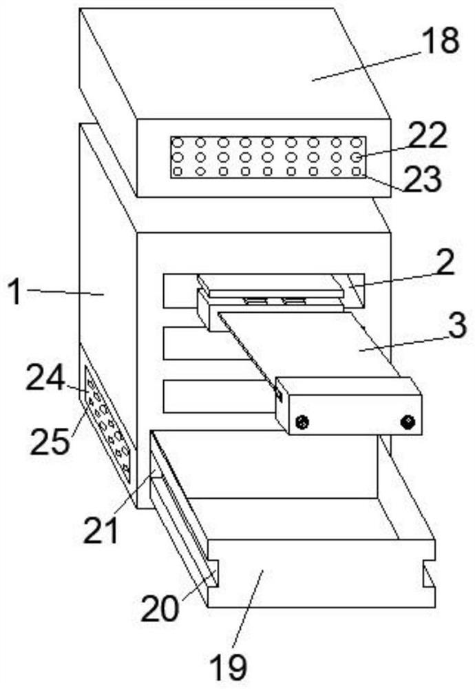
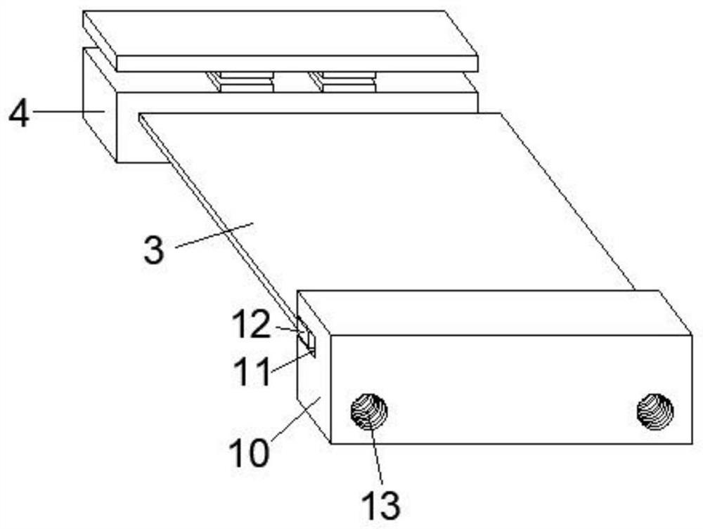
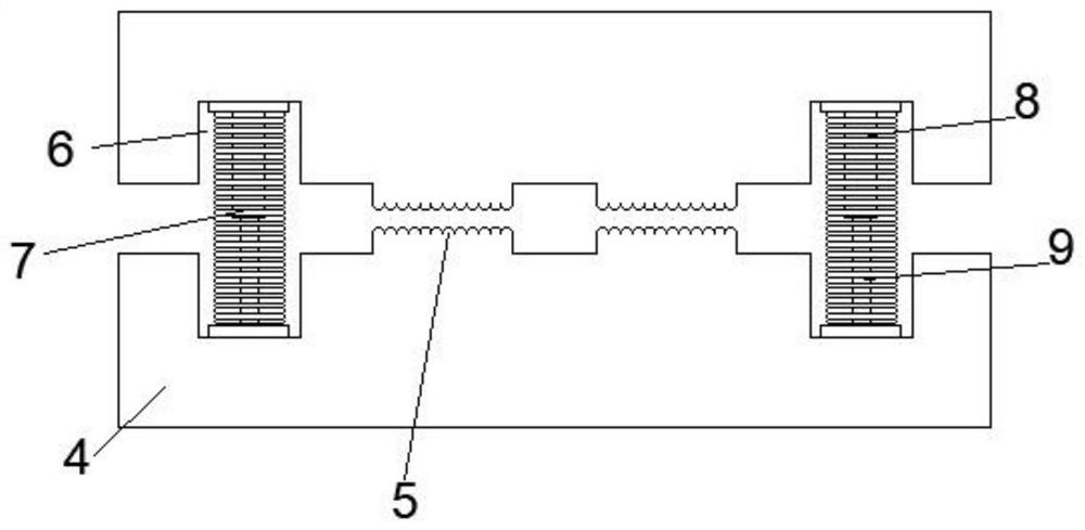
[0024] see Figure 1-5 , In this embodiment: an industrial environmental protection equipment for biological pollutants, including an equipment main body 1, a cavity 2 is arranged inside the equipment main body 1, a filter screen 3 is arranged inside the cavity 2, and a plywood 4 is arranged on one side of the filter screen 3, The clamping plate 4 is provided with a pressure block 5, and spring grooves 6 are provided on both sides of ...


PUM


Abstract

The invention discloses biological pollutant industrial environmental protection equipment which comprises an equipment body, a cavity is formed in the equipment body, a filter screen is arranged in the cavity, a clamping plate is arranged on one side of the filter screen, a pressing block is arranged in the clamping plate, spring grooves are formed in the two sides of the pressing block, and extension springs are arranged in the spring grooves. A first telescopic rod is arranged in the extension spring, a second telescopic rod is arranged at the bottom of the first telescopic rod, and a fixing plate is arranged on the side, away from the clamping plate, of the filter screen. According to the biological pollutant industrial environmental protection equipment, by arranging the clamping plates and the fixing plates, the purposes of facilitating replacement of a filter screen, simplifying disassembly and assembly of the filter screen, reducing the working intensity of workers and improving the working efficiency can be achieved, by arranging a dust collection box, a bearing and an air pipe, the application range of the equipment can be expanded, and the practicability is high. And dust in the equipment can be conveniently cleaned, and the practicability is enhanced.

Description

technical field [0001] The invention relates to the technical field of environmental protection equipment, in particular to an industrial environmental protection equipment for biological pollutants. Background technique [0002] Industrial environmental protection equipment refers to the ability to adsorb, decompose or convert various air pollution sources, air pollutants and other indoor biological pollutants. Pollutants mainly include bacteria, fungi, molds, viruses, dust mites, pollen, pet dander, organic components of organisms, etc., products that effectively improve air cleanliness, and currently mainly use household equipment and workshop purification equipment to remove indoor air pollution . [0003] The prior art has the following defects or problems: [0004] 1. When the existing environmental protection equipment is in use, the internal filter needs to be cleaned after a period of time, but the installation and removal of the filter is cumbersome, which increa...

Claims


Application Information

Patent Timeline
Patent Type & Authority Applications(China)
IPC IPC(8): B01D46/10B01D46/88
CPCB01D46/10B01D46/0002
Inventor 不公告发明人
Owner 山东高洁环保科技有限公司
Learn More