Breast feeding device for infants in obstetrical department
A technology for infants and breast milk, applied in the medical field, can solve the problems of increasing the physical fatigue of nursing staff, inconvenient breastfeeding of newborns, and increased physical burden of parturients, etc., to achieve the effects of convenient breastfeeding, convenient operation, and energy saving
- Summary
- Abstract
- Description
- Claims
- Application Information
AI Technical Summary
Problems solved by technology
Method used
Image
Examples
Embodiment 1
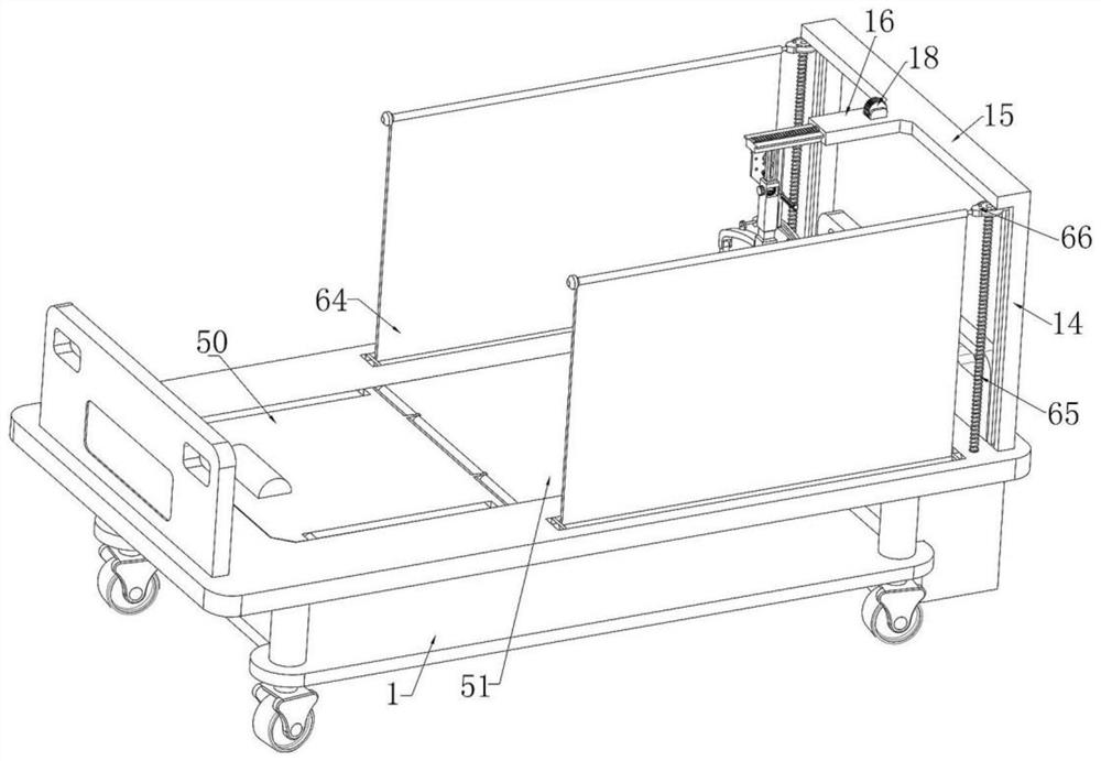
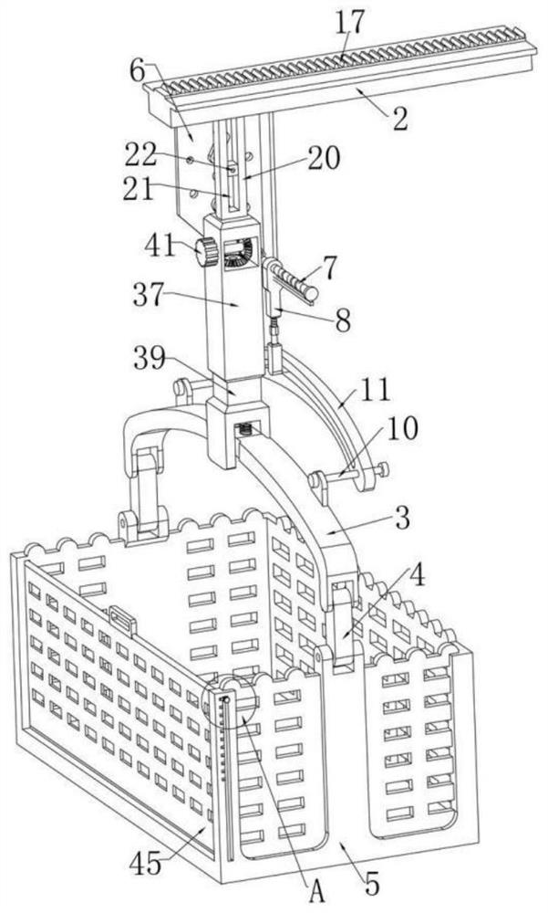
[0040] Example one, as Figure 1-3As shown in the figure, an obstetric infant breastfeeding device includes a nursing bed body 1, a support device is fixedly connected to the right end of the nursing bed body 1, and a T-shaped plate 2 is slidably installed on the upper end of the support device. The bottom of the template 2 is slidably installed with an adjusting device, the lower end of the adjusting device is rotatably installed with a swing rod 3, the swing rod 3 is in a curved shape, and the front and rear ends of the swing rod 3 are respectively rotated and installed with a ring rod 4 , a crib 5 is rotatably connected between the two annular rods 4, and the crib 5 is used to place a baby. The lower end of the side plate 6 is rotatably installed with a reciprocating screw rod 7 located on the right side of the adjusting device, the reciprocating screw rod 7 is threadedly connected with a reciprocating plate 8, and the side plate 6 is fixedly connected with a reciprocating ...
Embodiment 2
[0043] Embodiment 2, on the basis of Embodiment 1, as Figure 1-2 As shown, the support device includes vertical rods 14 fixedly connected to the front and rear ends of the right side of the nursing bed 1, respectively, and a beam rod 15 is fixedly connected between the upper ends of the two vertical rods 14. The beam rods The left end of the middle part of 15 is fixedly connected with a horizontal plate 16, a T-shaped groove runs through between the left and right inside the horizontal plate 16, and a T-shaped plate 2 is slidably connected to the left and right in the T-shaped groove. The upper end of the T-shaped plate 2 A sliding rack 17 located in the T-shaped groove is fixedly connected, the upper end of the horizontal plate 16 is fixedly connected with a sliding gear plate, and a sliding gear 18 meshing with the sliding rack 17 is rotatably connected to the sliding gear plate. The horizontal plate 16 is fixedly connected with an adjusting motor that is coaxially and fixe...
Embodiment 3
[0045] Embodiment 3, on the basis of embodiment 2, as Figure 3-4 As shown, a sliding square groove 19 is formed at the bottom of the left end of the T-shaped plate 2, and the adjusting device includes a moving block 20 slidably connected in the sliding square groove 19. The left and right ends of the moving block 20 are respectively fixedly connected with For the reset springs located in the sliding square groove 19, the other end of each reset spring is fixedly connected to the T-type plate 2 respectively. The moving block 20 is provided with a sliding hole 21 in the up and down direction, and the sliding hole 21 slides up and down. A block 22 is connected, the bottom of the moving block 21 is fixedly connected with a telescopic device, the swing rod 3 is rotatably connected to the telescopic device, the side plate 6 is rotatably connected with a rotating rod 23, and the upper end of the rotating rod 23 A rotating rod is fixedly connected and rotatably connected to the side ...
PUM
 Abstract
Description
Claims
Application Information
 - R&D
- Intellectual Property
- Life Sciences
- Materials
- Tech Scout
- Unparalleled Data Quality
- Higher Quality Content
- 60% Fewer Hallucinations
Browse by: Latest US Patents, China's latest patents, Technical Efficacy Thesaurus, Application Domain, Technology Topic, Popular Technical Reports.
© 2025 PatSnap. All rights reserved.Legal|Privacy policy|Modern Slavery Act Transparency Statement|Sitemap|About US| Contact US: help@patsnap.com


