


Quick Research
Generate reliable direction feasibility study reports for your R&D in just a few steps.

Technical Q&A
Discover and master advanced knowledge NOW. Basics, ideas, possibilities, all at once.

Find Solutions
As an expert in R&D theories, this can generate solutions to your technical problems instantly.

Evaluate Feasibility
Analyze your overall solution with one click, know your potential R&D risks in advance.

Monitor Landscape
Get weekly tech updates, stay abreast of the latest tech innovations and key insights.
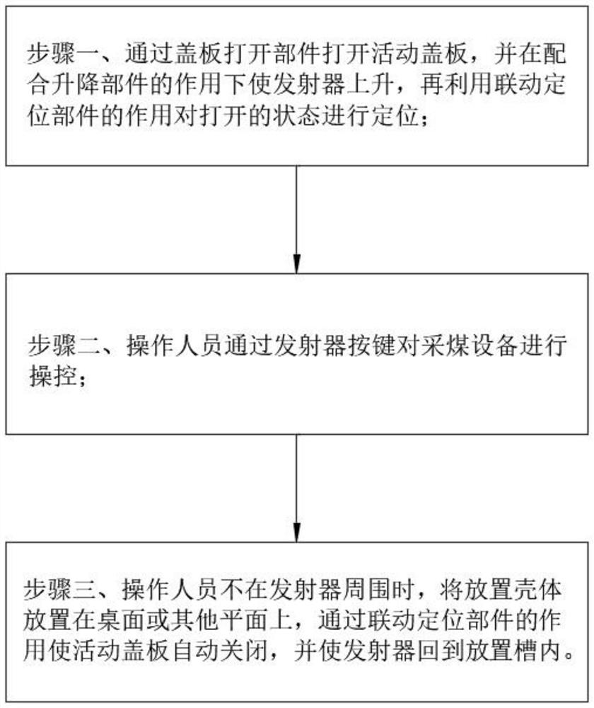
Positioning mechanism applied to emitter in Internet of Things device and positioning method thereof
A technology of positioning mechanism and transmitter, which is applied in the directions of cleaning methods, chemical instruments and methods, cleaning methods and utensils using gas flow, etc. Problems such as misoperation, to avoid misoperation, improve safety, and reduce misoperation
- Summary
- Abstract
- Description
- Claims
- Application Information
AI Technical Summary
Problems solved by technology
Method used
Image

Examples
Embodiment approach
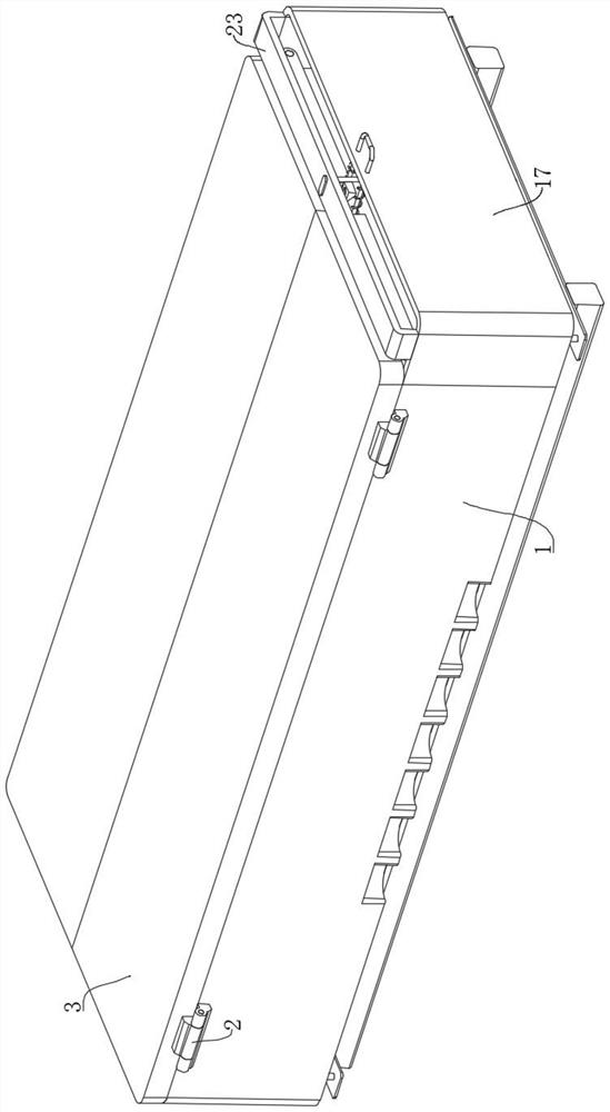
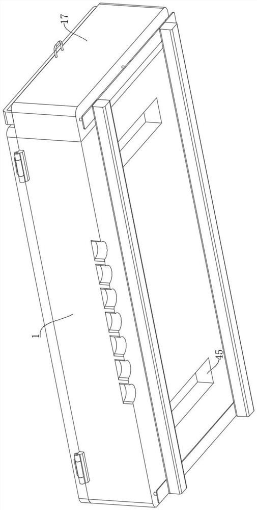
[0048] As an embodiment of the present invention, the cover plate opening member includes a connecting frame 17 and a sliding groove 18. The connecting frame 17 is fixedly connected to one side of the placing casing 1, and the sliding groove 18 is opened on the top of the placing casing 1 and is close to the connecting frame. At the position of 17, an extrusion block 19 is placed in the sliding groove 18, and a U-shaped rod 20 is fixedly connected to one side of the extrusion block 19. The U-shaped rod 20 is slidably inserted on one side of the connection frame 17, and the U-shaped rod 20 Both ends of the second spring 21 are sleeved with a second spring 21. Both ends of the second spring 21 are fixedly connected to one side of the extrusion block 19 and the inner wall of the connecting frame 17, and the connecting frame 17 rotates close to the side where the housing 1 is placed. Two flipping rods 22 are connected, one side of the flipping rod 22 close to the extrusion block 19...
PUM
 Abstract
Description
Claims
Application Information
 - R&D Engineer
- R&D Manager
- IP Professional
- Industry Leading Data Capabilities
- Powerful AI technology
- Patent DNA Extraction
Browse by: Latest US Patents, China's latest patents, Technical Efficacy Thesaurus, Application Domain, Technology Topic, Popular Technical Reports.
© 2024 PatSnap. All rights reserved.Legal|Privacy policy|Modern Slavery Act Transparency Statement|Sitemap|About US| Contact US: help@patsnap.com