


Quick Research
Generate reliable direction feasibility study reports for your R&D in just a few steps.

Technical Q&A
Discover and master advanced knowledge NOW. Basics, ideas, possibilities, all at once.

Find Solutions
As an expert in R&D theories, this can generate solutions to your technical problems instantly.

Evaluate Feasibility
Analyze your overall solution with one click, know your potential R&D risks in advance.

Monitor Landscape
Get weekly tech updates, stay abreast of the latest tech innovations and key insights.
Outdoor new energy street lamp with deinsectization function
A new energy and functional technology, which is applied in the direction of the internal power supply, the device for capturing or killing insects, outdoor lighting, etc., can solve the problems of small range of mosquito killing, low efficiency, and inability to kill mosquitoes, etc., to achieve convenience cleaning effect
- Summary
- Abstract
- Description
- Claims
- Application Information
AI Technical Summary
Problems solved by technology
Method used
Image


Examples
Embodiment 1
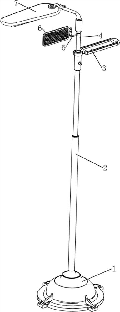
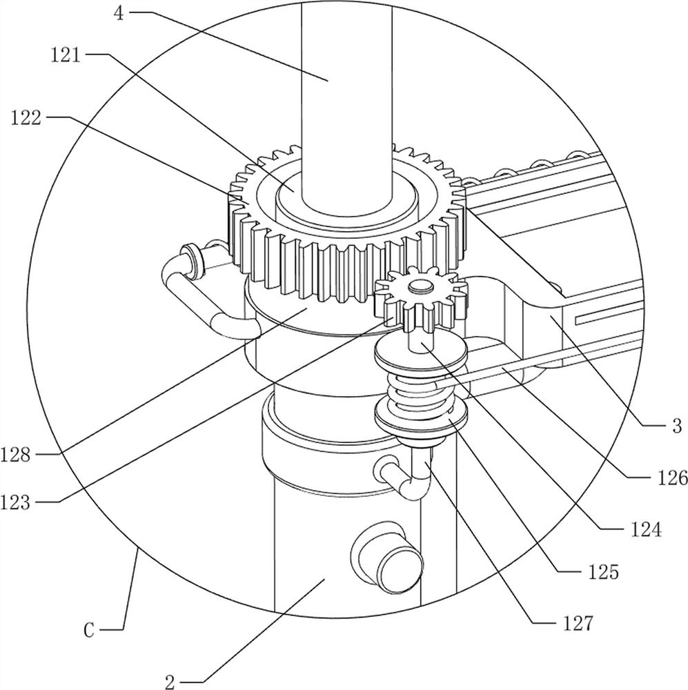
[0089] An outdoor new energy street light with insect control function, please refer to figure 1 , figure 2 , image 3 and Figure 4 , including a base 1, a support rod 2, a first lamp 3, a first rotating sleeve 4, a first fixed column 5, an insect control net 6, a second lamp 7, a condensing mechanism 8 and a rotating mechanism 9, the top of the base 1 is welded There is a support rod 2, the upper part of the support rod 2 is welded with a first lamp 3, the first lamp 3 is used to illuminate pedestrians, the top of the first lamp 3 is set in a concave shape, and the upper part of the support rod 2 is rotatably connected with a first rotating sleeve 4 , the first rotating cover 4 is located on the upper side of the first lamp 3, the first fixed column 5 is welded on the upper left side of the first rotating cover 4, and the first fixed column 5 is slidably connected with an insect killing net 6 for killing mosquitoes , the upper left side of the support rod 2 is fixed with...
Embodiment 2
[0094] On the basis of Example 1, see image 3 and Figure 8 , and also includes a shaking mechanism 10, the shaking mechanism 10 is used to drive the insecticide net 6 to shake, and the shaking mechanism 10 includes a first bump 101, a first linear spring 102, a fixed plate 103 and a second bump 104. A first bump 101 is welded on the right side of the net 6, a first linear spring 102 is connected between the lower right side of the insecticide net 6 and the first fixed column 5, a fixed plate 103 is welded on the upper part of the support rod 2, and the top of the fixed plate 103 is welded. Three second bumps 104 are welded on the right side, and the first bumps 101 are in contact with the second bumps 104 after moving.
[0095] When the first fixing post 5 drives the insecticide net 6 to rotate, it drives the first bump 101 to rotate. When the first bump 101 rotates to contact the second bump 104, under the cooperation of the first linear spring 102, The insecticide net 6 ...
PUM
 Abstract
Description
Claims
Application Information
 - R&D Engineer
- R&D Manager
- IP Professional
- Industry Leading Data Capabilities
- Powerful AI technology
- Patent DNA Extraction
Browse by: Latest US Patents, China's latest patents, Technical Efficacy Thesaurus, Application Domain, Technology Topic, Popular Technical Reports.
© 2024 PatSnap. All rights reserved.Legal|Privacy policy|Modern Slavery Act Transparency Statement|Sitemap|About US| Contact US: help@patsnap.com