Concrete pouring structure of super high-rise steel pipe column

A technology for concrete and steel pipe columns, which is applied in the field of concrete pouring, and can solve problems such as tediousness and increased construction difficulty

Active Publication Date: 2022-06-28
HUADONG BUILDING CO LTD OF CHINA CONSTR FIFTH ENG BUREAU +2
View PDF6 Cites 0 Cited by
  • Summary
  • Abstract
  • Description
  • Claims
  • Application Information

AI Technical Summary

Problems solved by technology

[0003] Aiming at the deficiencies of the existing technology, the present invention provides a concrete pouring structure for super high-rise steel pipe columns, in order to solve the problem in the prior art that the process of concrete pouring for super high-rise steel columns is relatively cumbersome and increases the difficulty of construction

Method used


Image

  • Concrete pouring structure of super high-rise steel pipe column
  • Concrete pouring structure of super high-rise steel pipe column
  • Concrete pouring structure of super high-rise steel pipe column

Examples


Embodiment Construction

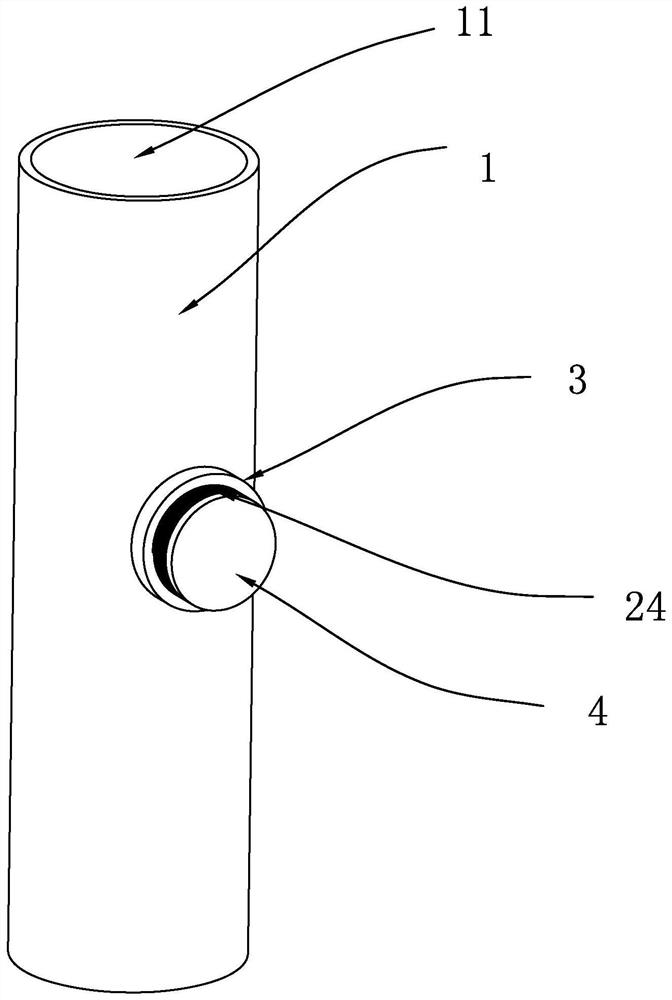
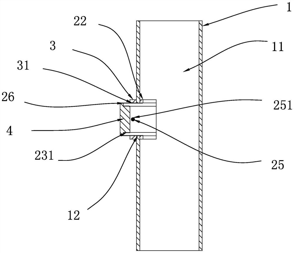
[0026] The present invention provides a concrete pouring structure of a super high-rise steel pipe column, including a steel column 1, a pouring cavity 11 is hollowed out along the height direction of the steel column 1, and an outer wall of the steel column 1 is provided for external operators to pour The clamping hole 12 for pouring concrete fluid in the cavity 11, the clamping hole 12 is arranged in communication with the pouring cavity 11, the clamping hole 12 is provided with a drainage assembly for guiding the flow of the external concrete fluid, and the drainage assembly includes two. There are two semi-cylindrical drainage columns 21, and two drainage columns 21 are arranged opposite to each other. One end of the drainage columns 21 is the insertion end for inserting into the casting cavity 11, and the other end is the drainage end located outside the steel column 1. The outer wall of the insertion end of the drainage column 21 is provided with an arc-shaped plate 22 fo...


PUM


Abstract

The concrete pouring structure of the super high-rise steel pipe column comprises a steel column, a pouring cavity is formed in the steel column in the height direction of the steel column in a hollow mode, a clamping hole allowing an external operator to pour concrete fluid into the pouring cavity is formed in the outer wall of the steel column, and the clamping hole communicates with the pouring cavity; a drainage assembly used for guiding the flowing direction of external concrete fluid is arranged on the clamping hole. The problems that in the prior art, the concrete pouring process of the super high-rise steel column is tedious, and the construction difficulty is increased are solved.

Description

technical field [0001] The invention relates to the technical field of concrete pouring, in particular to a concrete pouring structure of a super high-rise steel pipe column. Background technique [0002] In the construction process of the existing house structure, super high-rise steel columns are usually placed at the designated construction sites for house construction, and the super-high-rise steel columns are hollow structures, so that in the later construction period, the construction personnel will pay attention to the steel columns. Concrete fluid is poured inside, and because the height of the super high-rise steel column is too high, the operator can only pour concrete into the interior from the top of the steel column, but the top-down pouring process and pouring method are cumbersome and greatly delayed. The construction period is shortened, and the construction difficulty is also increased. SUMMARY OF THE INVENTION [0003] Aiming at the deficiencies of the p...

Claims


Application Information

Patent Timeline
IPC IPC(8): E04C3/34E04G21/02
CPCE04C3/34E04G21/02Y02E10/20
Inventor 陈超周铮陈劲白金鑫周赤晨
Owner HUADONG BUILDING CO LTD OF CHINA CONSTR FIFTH ENG BUREAU
Why Eureka
Try Eureka