Automatic ink supply writing brush
A brush and automatic technology, applied to other ink pens, printing, writing utensils, etc., can solve the problems of easy crystallization of residual ink, blockage of moisturizing paths, affecting writing and painting creation, etc.
- Summary
- Abstract
- Description
- Claims
- Application Information
AI Technical Summary
Problems solved by technology
Method used
Image
Examples
Embodiment 1
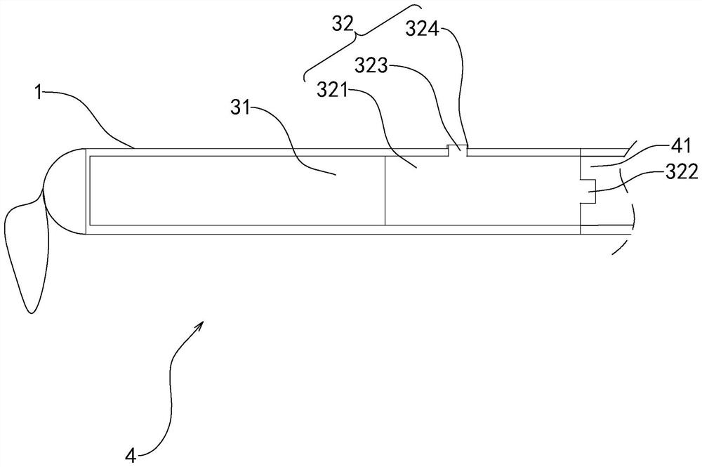
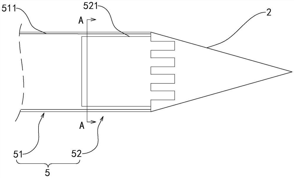
[0035] refer to figure 1 , which is an automatic ink supply brush disclosed in the application, comprising a pen holder 1 and a pen head 2, the pen head 2 is arranged at one end of the pen holder 1 in the length direction, and the pen holder 1 is provided with a power control unit 3, an ink storage unit 4 and an adjustment unit 5. The ink is stored in the ink storage unit 4, and the power control unit 3 is used to apply pressure to the ink storage unit 4, so that the ink in the ink storage unit 4 moves the ink in the direction of the pen head 2 under the pressure of the pressure, thereby realizing automatic supply. At the same time, the adjustment unit 5 is used to adjust the real-time ink supply, so as to reduce the occurrence of ink thick or light in the ink supply process.
[0036] refer to figure 1 and figure 2 , the power control unit 3 includes a power supply assembly 31 for providing electrical energy and a power assembly 32 , the power supply assembly 31 includes a ...
Embodiment 2
[0040] refer to Figure 5 , according to the power control unit 3 in the second embodiment of the present application, the power control unit 3 also includes a power supply assembly 31 and a power assembly 32. The difference between the second embodiment and the first embodiment is that the power assembly 32 includes a micro motor 33 arranged in the pen holder 1. The motor 33 is provided with a push rod 331, and the push rod 331 is provided with a piston 332 abutting on the inner wall of the pen barrel 1. After starting the micro motor 33, the micro motor 33 is used to drive the push rod 331 to move, and the push rod 331 is used to drive the piston 332. The ink bag 41 is squeezed, so that the ink in the ink bag 41 automatically completes the ink pushing process.
[0041] refer to Image 6, the adjustment chamber 511 is provided with a micro-transport pump 53, and by setting the micro-transport pump 53 in the adjustment chamber 511, the speed of ink supply is controlled by one...
Embodiment 3
[0043] refer to Figure 7 , according to the power control unit 3 in the third embodiment of the present application, the power control unit 3 also includes a power supply assembly 31 and a power assembly 32. The difference between the third embodiment and the first embodiment is that the power assembly 32 includes a magnetic force block 34 arranged on the inner wall of the pen holder 1. The magnetic force A T-shaped push rod 341 is fixed on the block 34, and the T-shaped push rod 341 abuts on the inner wall of the pen holder 1. When the magnetic block 34 moves toward the pen head 2, the magnetic block 34 drives the T-shaped push rod 341 to push the ink bag 41 to move. At the same time, the power assembly 32 also includes a magnetic housing 6 sleeved on the outer wall of the pen holder 1. The magnetic housing 6 is connected to the controller, and the controller is used to control the magnetic housing 6 to generate magnetic lines of force, and then control the moving speed of th...
PUM
 Abstract
Description
Claims
Application Information
 - Generate Ideas
- Intellectual Property
- Life Sciences
- Materials
- Tech Scout
- Unparalleled Data Quality
- Higher Quality Content
- 60% Fewer Hallucinations
Browse by: Latest US Patents, China's latest patents, Technical Efficacy Thesaurus, Application Domain, Technology Topic, Popular Technical Reports.
© 2025 PatSnap. All rights reserved.Legal|Privacy policy|Modern Slavery Act Transparency Statement|Sitemap|About US| Contact US: help@patsnap.com


