
Automatic label printing device for cylindrical workpiece surface

A workpiece surface and marking technology, applied in printing, printing machines, rotary printing machines, etc., can solve the problems of inability to discharge materials, high cost, and high energy consumption

Inactive Publication Date: 2021-07-06
李志聪
View PDF0 Cites 2 Cited by
  • Summary
  • Abstract
  • Description
  • Claims
  • Application Information

AI Technical Summary

Problems solved by technology

[0003] For the marking of products, it is generally realized by a marking machine. When the existing marking device is in use, the workpiece is generally placed in the box first, and then falls on the conveying device through the discharge port to transmit the workpiece. During the discharge process, the workpiece is easily stuck in the discharge port, causing the problem that the material cannot be discharged. At the same time, the existing marking device generally requires multiple output terminals to be driven separately for the transmission of the workpiece and the operation of the marking mechanism, which consumes a lot of energy. energy, the cost is relatively large

Method used


Image

  • Automatic label printing device for cylindrical workpiece surface
  • Automatic label printing device for cylindrical workpiece surface
  • Automatic label printing device for cylindrical workpiece surface

Examples


Embodiment Construction

[0024] The present invention is described in further detail now in conjunction with accompanying drawing. These drawings are all simplified schematic diagrams, which only illustrate the basic structure of the present invention in a schematic manner, so they only show the configurations related to the present invention.

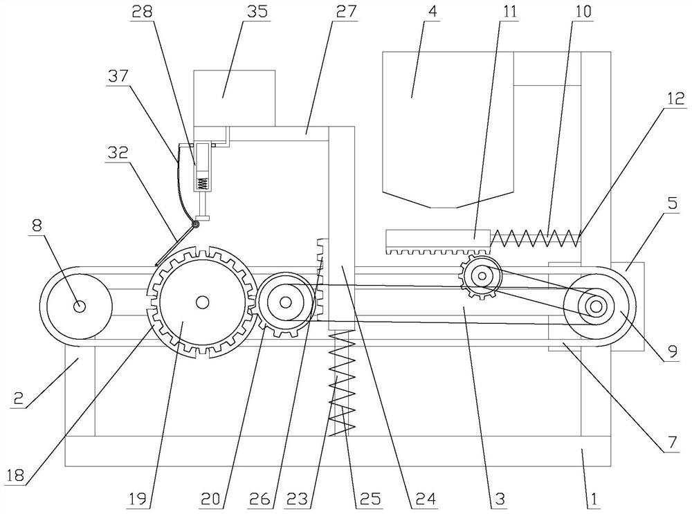
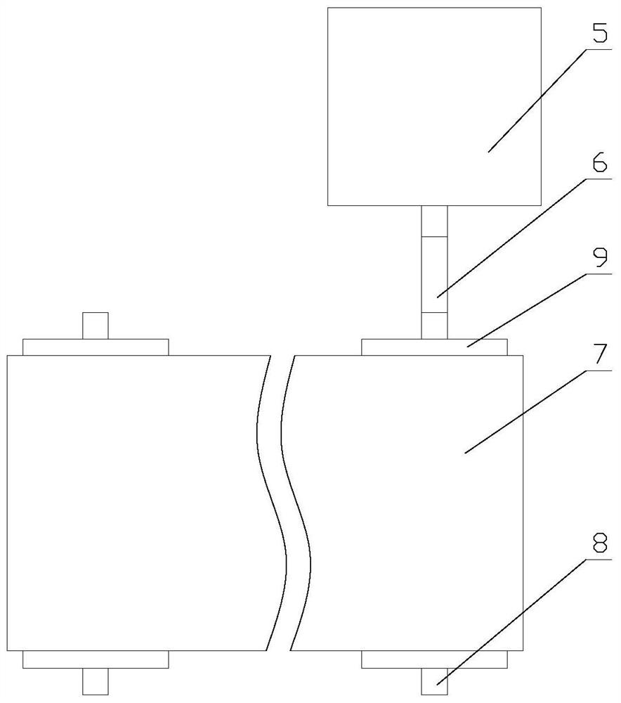
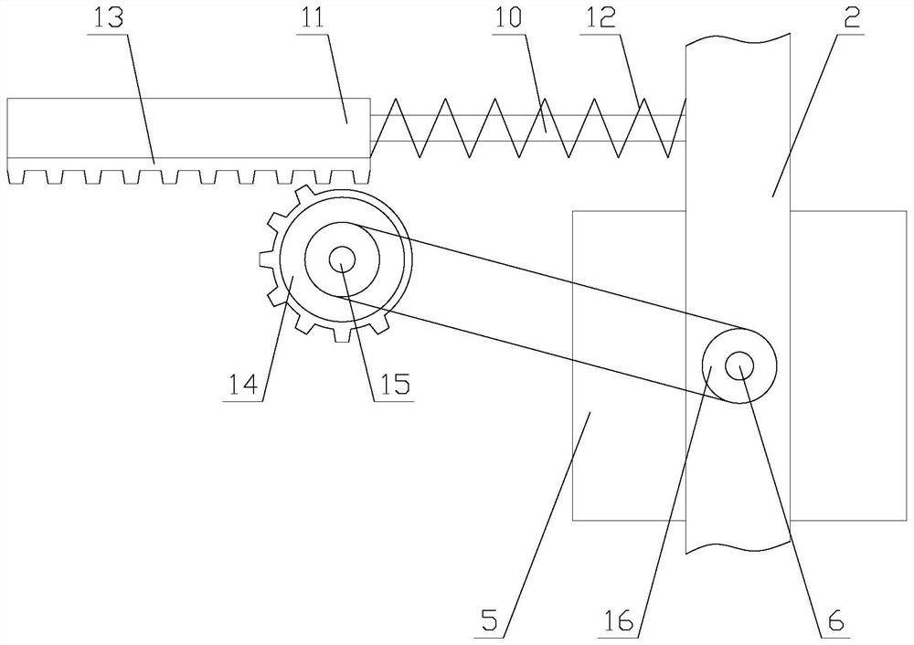
[0025] Such as figure 1 As shown, a cylindrical workpiece surface marking device includes a base 1, a support rod 2, a bottom plate 3, a box body 4, a transmission mechanism, a discharge mechanism and a marking mechanism. There are two support rods 2, two The poles 2 are respectively arranged at both ends of the base 1, the bottom plate 3 is arranged between the two poles 2, the box 4 is arranged on one of the poles 2, and the bottom of the box 4 is provided with a discharge mouth, the transfer mechanism is set on the bottom plate 3, the discharge mechanism is set at the discharge port, and the marking mechanism is set in the middle of the bottom plate 3;

...


PUM


Abstract

The invention relates to an automatic label printing device for a cylindrical workpiece surface. The automatic marking device comprises a base, a supporting rod, a bottom plate, a box body, a conveying mechanism, a discharging mechanism and a label printing mechanism, the conveying mechanism is arranged on the bottom plate, the discharging mechanism is arranged at a discharging port, and the label printing mechanism is arranged in the middle of the bottom plate. According to the automatic marking device, discharging is achieved through the discharging mechanism, conveying of the workpieces is achieved through the conveying mechanism, label printing of the workpieces is achieved through the label printing mechanism, compared with an existing label printing device, discharging and conveying of the workpieces and operation of the label printing mechanism can be achieved through one output end, energy is saved, meanwhile, linkage is adopted for the conveying mechanism and label printing, online label printing of the workpiece is realized, the efficiency is improved, a pure mechanical structure is adopted in linkage, the stability of the device is improved, the service life of the device is prolonged, and compared with the existing label printing mechanism, sufficient ink is always kept on a printing plate through an ink adding unit and an ink supplementing unit, so that the label printing effect is improved.

Description

technical field [0001] The invention relates to an automatic marking device on the surface of a cylindrical workpiece. Background technique [0002] Printing is to silk screen or print pictures on solid objects, such as printing on books, products, etc., including wet ink printing, hot stamping and electronic printing. [0003] For the marking of products, it is generally realized by a marking machine. When the existing marking device is in use, the workpiece is generally placed in the box first, and then falls on the conveying device through the discharge port to transmit the workpiece. During the discharge process, the workpiece is easily stuck in the discharge port, causing the problem that the material cannot be discharged. At the same time, the existing marking device generally requires multiple output terminals to be driven separately for the transmission of the workpiece and the operation of the marking mechanism, which consumes a lot of energy. energy, the cost is r...

Claims


Application Information

Patent Timeline
Patent Type & Authority Applications(China)
IPC IPC(8): B41F17/10B41F31/02
CPCB41F17/10B41F31/02
Inventor 李志聪
Owner 李志聪
Learn More