
Modeling method of power electronic device

A technology of power electronic devices and modeling methods, which is applied in CAD circuit design, complex mathematical operations, special data processing applications, etc., can solve problems such as long simulation time and large memory requirements, and achieve the effect of improving simulation speed

Pending Publication Date: 2022-06-24
GLOBAL ENERGY INTERCONNECTION RES INST CO LTD +1
View PDF0 Cites 0 Cited by
  • Summary
  • Abstract
  • Description
  • Claims
  • Application Information

AI Technical Summary

Problems solved by technology

[0003] Therefore, the technical problem to be solved by the present invention is to overcome the defects of large memory requirements and long simulation time in the modeling method of power electronic devices in the prior art, thereby providing a modeling method of power electronic devices

Method used


Image

  • Modeling method of power electronic device
  • Modeling method of power electronic device
  • Modeling method of power electronic device

Examples


Embodiment

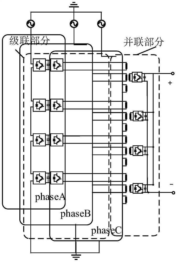
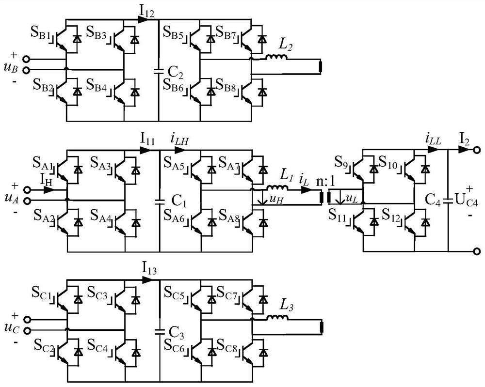
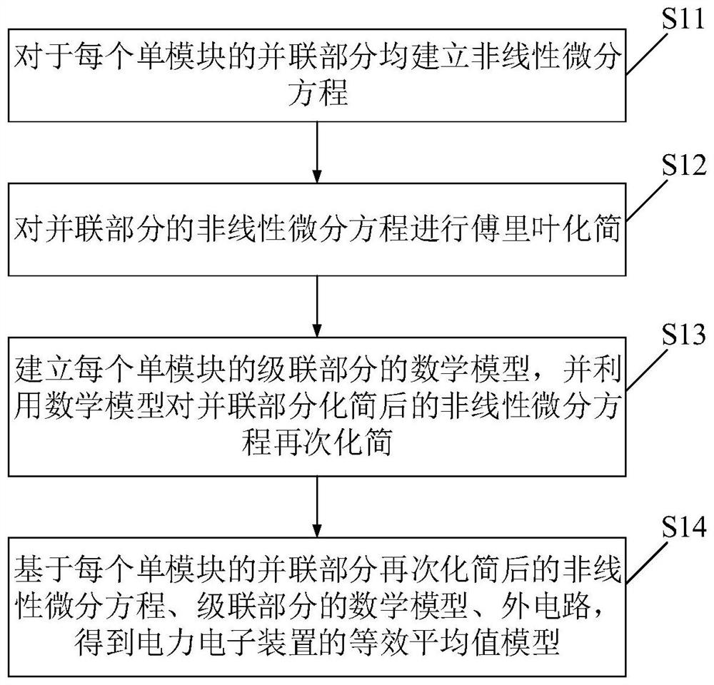
[0031] Embodiments of the present invention provide a modeling method for a power electronic device, such as figure 1 As shown, the power electronic device consists of a number of single modules, such as figure 2 As shown, each phase of the input end of each single module is constituted by an active bridge module, and the output end of each single module is constituted by an active bridge module, wherein the active bridges of the same phase of the power electronic device are formed by an active bridge module. Cascaded connection, the active bridges at the output are connected in parallel, such as image 3 As shown, the modeling methods include:

[0032] Step S11: Establish a nonlinear differential equation for the parallel part of each single module.

[0033] Specifically, for the parallel part of each single module, the embodiment of the present invention first selects a state variable, and uses switching functions to perform equivalence on the switching devices involved i...


PUM


Abstract

The invention discloses a modeling method of a power electronic device. The modeling method comprises the following steps: establishing a nonlinear differential equation for a parallel part of each single module; fourier simplification is carried out on the nonlinear differential equation of the parallel connection part; establishing a mathematical model of the cascade part of each phase of each single module, and using the mathematical model to simplify the nonlinear differential equation after the parallel part is simplified again; the equivalent average value model of the power electronic device is obtained based on a nonlinear differential equation obtained after the parallel part of each single module is simplified again, a mathematical model of the cascade part and an external circuit, so that the simulation speed of the model is remarkably improved under the condition that the precision is stable, and the simulation efficiency is improved. Moreover, the average value model can effectively simulate the external characteristics of the power electronic device, neglects the internal dynamic characteristics, and has important theoretical significance and application value.

Description

technical field [0001] The invention relates to the field of power system simulation, in particular to a modeling method of a power electronic device. Background technique [0002] With the increasing demand for large-scale intermittent distributed renewable energy generation and grid integration, the traditional single-source, single-ended AC distribution network is rapidly developing into a multi-source, multi-terminal flexible DC or AC-DC hybrid distribution network. Power Electronic Transformer (PET), as the core equipment of "energy router", realizes voltage conversion and power transmission through power electronic technology. Among various types of PET topologies, multi-active bridge PETs, which contain multiple AC and DC ports for interconnecting multi-voltage and multi-power energy networks, are becoming increasingly popular due to their more compact structure and lower cost. welcome. In recent years, high-speed equivalent modeling and simulation of various PET st...

Claims


Application Information

Patent Timeline
IPC IPC(8): G06F30/36G06F17/14G06F17/13
CPCG06F30/36G06F17/13G06F17/14
Inventor 王英沛宋洁莹刘宗烨于弘洋陆振纲杨士慧王春义魏振
Owner GLOBAL ENERGY INTERCONNECTION RES INST CO LTD
Learn More