Assembling and welding clamp suitable for steel structure

A technology for welding jigs and steel structures, applied in welding equipment, auxiliary welding equipment, welding/cutting auxiliary equipment, etc., can solve problems such as large space jig size, troublesome locking jig angle, difficulty in obtaining high adjustment accuracy, etc., to achieve The structure is simple and reliable, and the effect of fewer parts

Active Publication Date: 2022-06-17
深圳市东信海洋机械工程有限公司
View PDF13 Cites 0 Cited by
  • Summary
  • Abstract
  • Description
  • Claims
  • Application Information

AI Technical Summary

Problems solved by technology

[0003] Most of the welding connection features of the existing steel structures are two points, one is that the angle of the two butt steel structures is variable, and the other is that the profiles are realigned when the butt parts of the two butt steel structures are staggered. Most of the angle adjustment discs of the steel structure docking fixtures are manually pulled to complete the angle adjustment. This adjustment method is difficult to obtain high adjustment accuracy, and there is no temporary position holding device after the adjustment is completed. It is troublesome to lock the angle of the fixture. This problem can be circumvented by using the angle adjustment structure of the gear meshing scheme, but the gear meshing scheme will take up a lot of space and the volume of the fixture is large

Method used


Image

  • Assembling and welding clamp suitable for steel structure
  • Assembling and welding clamp suitable for steel structure
  • Assembling and welding clamp suitable for steel structure

Examples


Embodiment Construction

[0028] The technical solutions in the embodiments of the present invention will be clearly and completely described below with reference to the accompanying drawings in the embodiments of the present invention. Obviously, the described embodiments are only a part of the embodiments of the present invention, rather than all the embodiments.

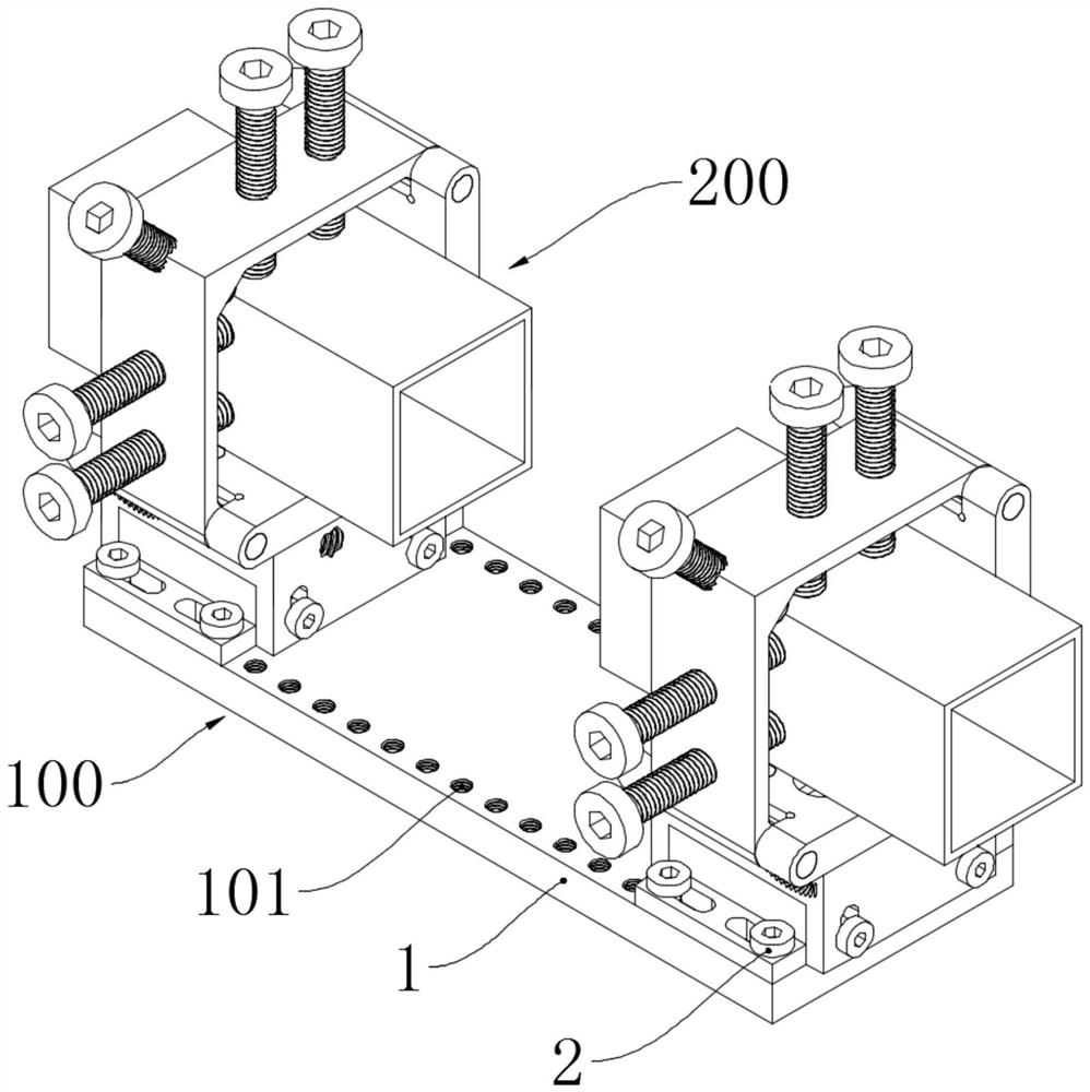
[0029] See e.g. Figure 1-Figure 2 An assembly welding fixture suitable for a steel structure shown includes a bottom assembly 100 and a top assembly 200 arranged above it. The bottom assembly 100 includes a bottom support plate 1 and a support plate screw 2 installed above it. The bottom support plate The upper surface of 1 is smoothed by a grinding machine, and the bottom plate 1 after grinding is subjected to hardening treatment on the outside. The distribution spacing corresponds to the length and distribution spacing of the table edge fixing grooves 1403. The support plate screws 2 are located inside the support plate screw holes 101,...


PUM


Abstract

The invention discloses an assembling and welding clamp suitable for a steel structure, and belongs to the technical field of steel structure machining forming, the assembling and welding clamp comprises a bottom assembly and a top assembly arranged above the bottom assembly, the bottom assembly comprises a bottom supporting plate and a supporting plate screw installed above the bottom supporting plate, and the top assembly comprises an upper rotary table. A top clamping support is connected to the upper portion of the upper rotary table through a support end shaft, a workpiece fixing bolt in threaded connection with the top clamping support is arranged in the top clamping support, a height supporting table is arranged below the upper rotary table, a bottom table is arranged below the height supporting table, and an intruding shaft and a middle shaft which are fixed to the height supporting table are arranged in the height supporting table. The upper end of the middle shaft is intruded into the upper rotary table, the lower end of the middle shaft is located in the bottom table, a flat angle locking screw, a horizontal adjusting jackscrew and a height adjusting jackscrew which are in threaded connection with the height supporting table are screwed in the height supporting table, and the flat angle locking screw penetrates through the horizontal part of the upper rotary table. And the fixed-angle butt joint of a steel structure can be met.

Description

technical field [0001] The invention belongs to the technical field of steel structure processing and forming B23K37, and particularly relates to an assembled welding fixture suitable for steel structures. Background technique [0002] Steel is a general term for iron-carbon alloys with a carbon content between 0.02% and 2.11%. Due to the characteristics of high strength, light weight, good overall rigidity, and strong resistance to change, steel is an indispensable material in human production and life. There is a missing part. After the steel is processed and formed, the steel parts are further processed by welding, bolting or rivet connection to produce the steel structure required for actual production. [0003] The welding connection characteristics of the existing steel structures are mostly two points. One is that the angles of the two butt-jointed steel structures are variable; Most of the angle adjustment discs of the clamps connected to the steel structure are man...

Claims


Application Information

Patent Timeline
Patent Type & Authority Applications(China)
IPC IPC(8): B23K37/04
CPCB23K37/0443
Inventor 林高行林思远
Owner 深圳市东信海洋机械工程有限公司
Why Eureka
Try Eureka