
Compressor pump body structure and compressor

A compressor and pump body technology, applied in the direction of machines/engines, pumps, pump components, etc., can solve the problems of insufficient jet volume, refrigerant backflow, large assembly clearance volume, etc., to avoid refrigerant backflow, increase effective paths, and improve performance effect

Pending Publication Date: 2022-06-14
SHANGHAI HITACHI ELECTRICAL APPLIANCES CO LTD
View PDF0 Cites 0 Cited by
  • Summary
  • Abstract
  • Description
  • Claims
  • Application Information

AI Technical Summary

Problems solved by technology

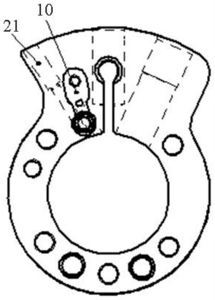
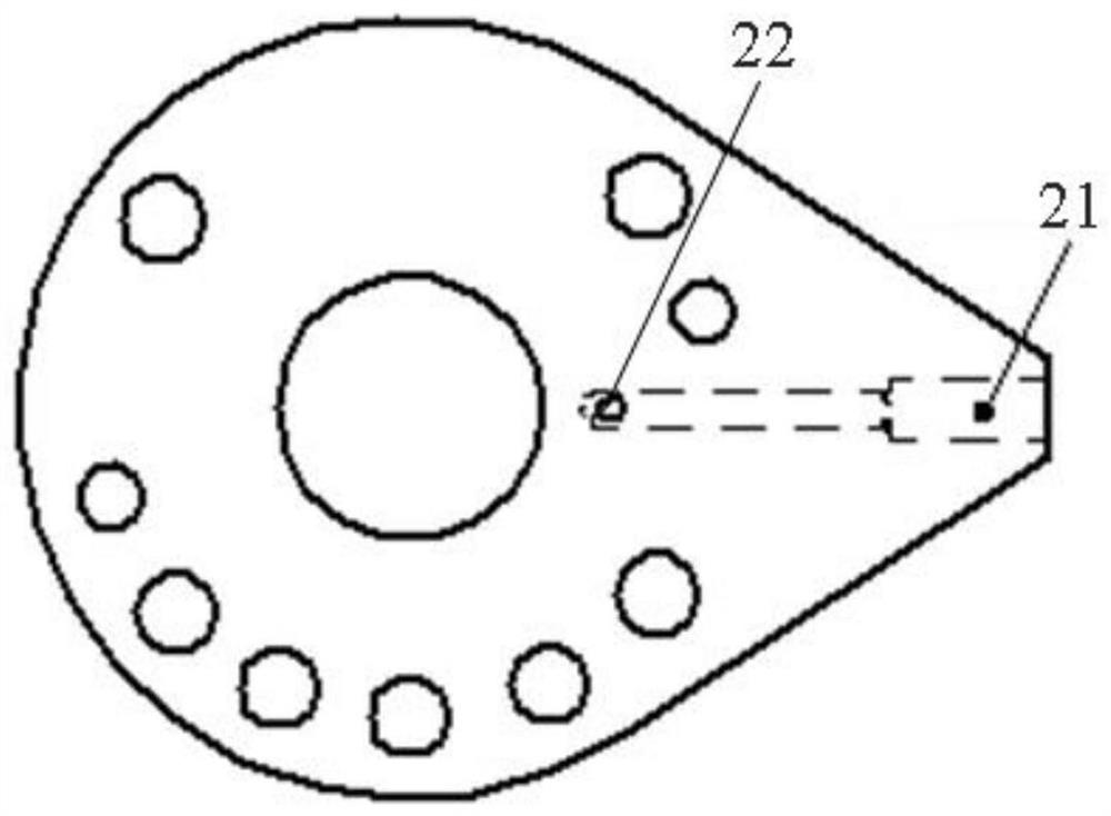
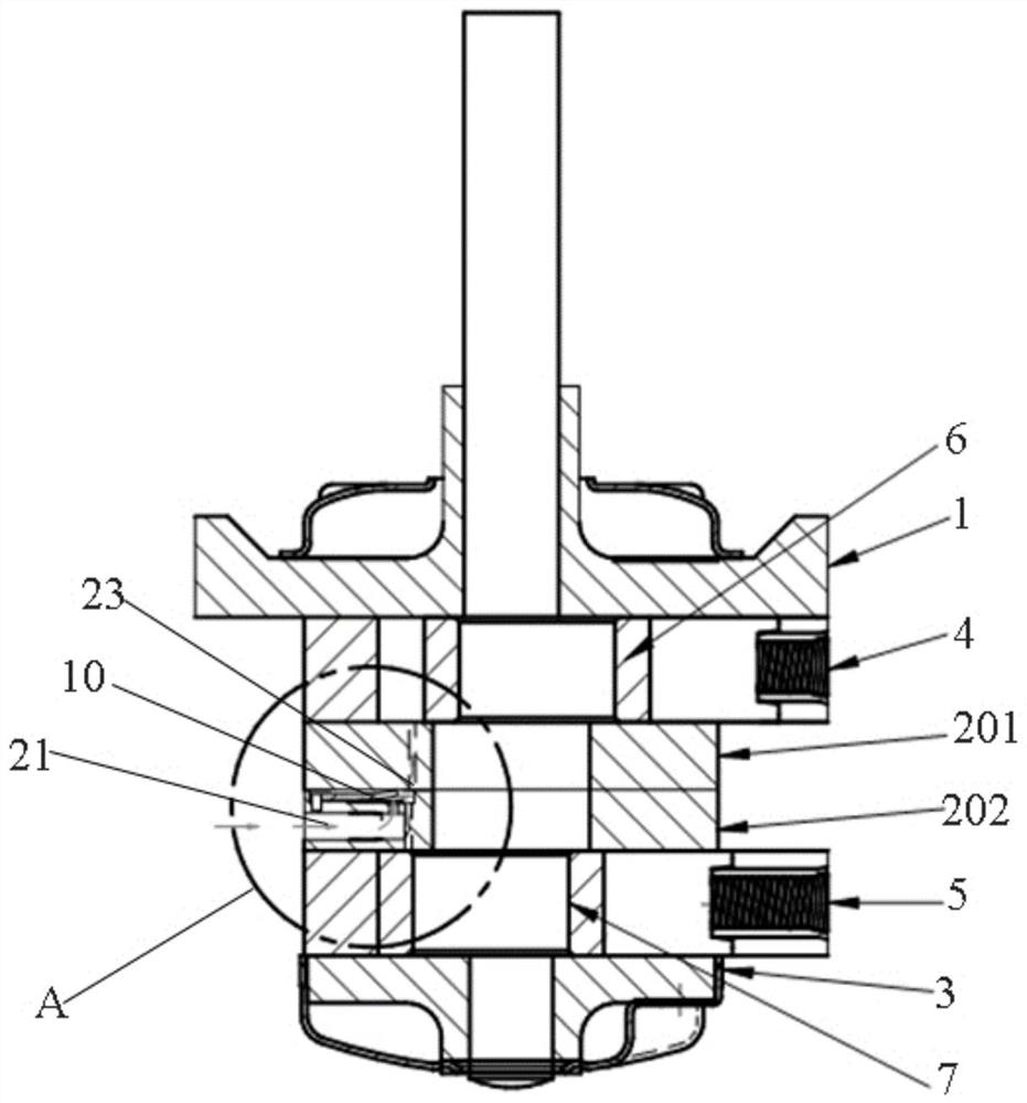
[0005] The purpose of the present invention is to provide a compressor pump body structure and compressor to solve the problems of large assembly clearance volume or insufficient air injection volume or refrigerant backflow in the air injection enthalpy increasing compressor in the prior art

Method used


Image

  • Compressor pump body structure and compressor
  • Compressor pump body structure and compressor
  • Compressor pump body structure and compressor

Examples


Embodiment Construction

[0028] The structure of a compressor pump body and the compressor proposed by the present invention will be further described in detail below with reference to the accompanying drawings and specific embodiments. The advantages and features of the present invention will become more apparent from the following description. It should be noted that, the accompanying drawings are all in a very simplified form and in inaccurate scales, and are only used to facilitate and clearly assist the purpose of explaining the embodiments of the present invention.

[0029] In the description of the present invention, it should be understood that the terms "center", "longitudinal", "lateral", "length", "thickness", "upper", "lower", "front", "rear", " The orientation or positional relationship indicated by vertical, horizontal, top, bottom, inner, outer, axial, radial, circumferential, etc. is based on the drawings. The stated orientation or positional relationship is only for the convenience o...


PUM


Abstract

The compressor pump body structure comprises a first cylinder cover, a second cylinder cover, a first air cylinder and a second air cylinder, the first air cylinder and the second air cylinder are arranged between the first cylinder cover and the second cylinder cover and separated by a middle plate assembly, the middle plate assembly comprises two stacked middle plates, and valve seats are arranged on the opposite end faces of the two middle plates; a valve seat cavity of the valve seat is internally provided with an air spraying opening and a valve block which can separately cover the air spraying opening, the middle plate where the air spraying opening is located is provided with an air spraying and air inlet channel communicated with the air spraying opening in the radial direction, and the sides, exposed out of the first compression cavity and the second compression cavity, of the two middle plates are provided with an air spraying channel in the axial direction. The two air injection channels are both communicated with a valve seat cavity of the valve seat. The valve seats on the two middle plates are matched with the air injection channels to achieve enhanced vapor injection in the compression cavity, so that the communicating clearance volume is reduced, the effective path through which a refrigerant flows is increased, refrigerant backflow is avoided, and the performance of the compressor is improved.

Description

technical field [0001] The invention relates to the technical field of compressors, in particular to a compressor pump body structure and a compressor. Background technique [0002] The jet enthalpy compressor in the prior art is mainly to increase the capacity of the compressor, especially the heating capacity under low temperature conditions. The current jet enthalpy compressor is implemented in two ways: [0003] The first method is to set a valve seat on the exhaust port side of the cylinder. The general working process is that when the compressor suction ends, the pressure in the compression chamber is lower than the pressure of the refrigerant injection port, and the valve seat opens in one direction. When the gas is injected into the compression chamber, with the movement of the piston, the volume of the compression chamber gradually decreases, and the gas pressure in the compression chamber gradually increases. When the pressure in the compression chamber is equal to...

Claims


Application Information

Patent Timeline
Patent Type & Authority Applications(China)
IPC IPC(8): F04B25/00F04B39/00F04B39/12F04B39/10
CPCF04B25/005F04B39/0005F04B39/122F04B39/10
Inventor 张钧琰谢郦卿潘飞
Owner SHANGHAI HITACHI ELECTRICAL APPLIANCES CO LTD
Learn More