Rod clamping mechanism for efficient rod changing and wire drawing feeding device
A technology of feeding device and clamping rod, which is applied in manufacturing tools, glass manufacturing equipment, etc., to achieve the effect of reducing diameter size deviation, improving positioning accuracy, and convenient and quick operation.
Pending Publication Date: 2022-06-10
河南神玖天航新材料股份有限公司
View PDF0 Cites 0 Cited by
- Summary
- Abstract
- Description
- Claims
- Application Information
AI Technical Summary
Problems solved by technology
[0003] The object of the present invention is to provide a clamping rod mechanism for a high-efficiency rod changing wire drawing feeding device, which is used to solve the complicated and troublesome operation of the existing clamping rod mechanism, low efficiency and Technical problem of poor positioning accuracy of quartz rods
Method used
View moreImage
Smart ImageViewing Examples

Examples
Embodiment approach
Login to View More PUM
 Abstract
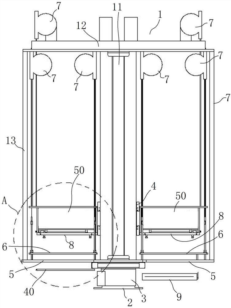
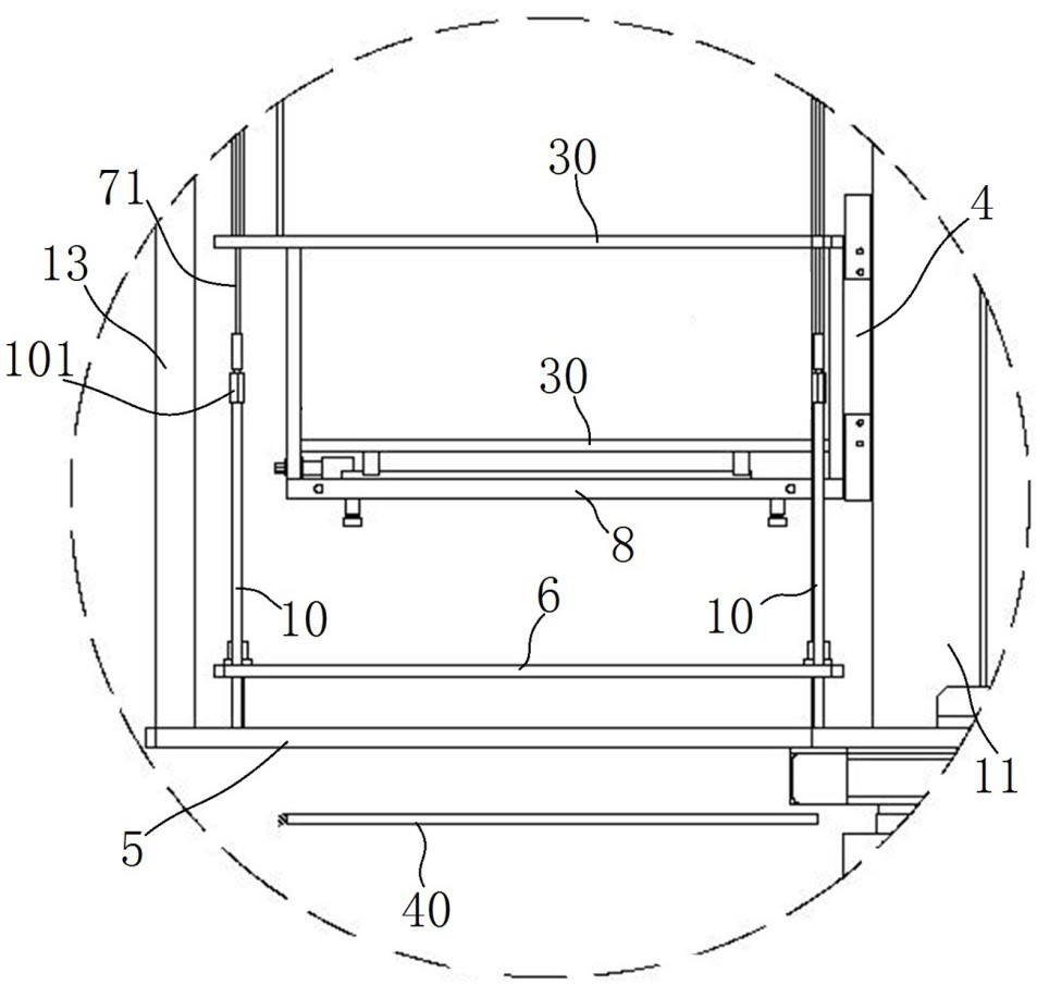
The invention relates to a rod clamping mechanism for an efficient rod changing and wire drawing feeding device. The rod clamping mechanism is used for solving the technical problems that an existing rod clamping mechanism is tedious and troublesome in operation, low in efficiency and poor in quartz rod positioning precision. The rod clamping mechanism for the efficient rod changing and wire drawing feeding device comprises a fixed clamping plate, a transverse guide rod, a movable clamping plate, a sliding rod and a driving mechanism. The sliding rod is driven by the driving mechanism to move so as to drive the at least two connecting rod groups to act, and each connecting rod group drives the two movable clamping plates to synchronously move towards the corresponding fixed clamping plates, so that the two rows of quartz rods are synchronously clamped. The quartz rod clamping device has the advantages of being convenient, fast and efficient to operate, high in quartz rod positioning precision and uniform and consistent in clamping force on all quartz rods.
Description
Technical field [0001] The present invention involves a coating mechanism for a high -efficiency switch to the feeding device. Background technique [0002] At present, the manufacturing method of quartz fiber is mainly made by the first -class drawing method. When the quartz rod is melted, the litter needs to use the device to drive multiple quartz rods through its corresponding burner to melt the quartz rods.In order to improve the efficiency, tensile quartz fiber is used to improve the efficiency. Generally, dozens to hundreds of quartz rods need to be made. Traditional sticks are tediously operated, low efficiency, unevenly clamped, and easy to clamp the stick mechanism.The poor shaking and positioning accuracy can easily lead to the position accuracy of the sandwiches that is held than the design requirements. The position deviation of the quartz rod directly affects the distance from the flame mouth, resulting in poor melting effect, unevenness, and affecting the final prod...
Claims
Login to View More Application Information
Patent Timeline
 Patent Type & Authority Applications(China)
IPC IPC(8): C03B37/025C03B37/03
CPCC03B37/025C03B37/03
Inventor 李泉涌李丽景
Owner 河南神玖天航新材料股份有限公司
Features
- Generate Ideas
- Intellectual Property
- Life Sciences
- Materials
- Tech Scout
- Unparalleled Data Quality
- Higher Quality Content
- 60% Fewer Hallucinations
Learn More Browse by: Latest US Patents, China's latest patents, Technical Efficacy Thesaurus, Application Domain, Technology Topic, Popular Technical Reports.
© 2025 PatSnap. All rights reserved.Legal|Privacy policy|Modern Slavery Act Transparency Statement|Sitemap|About US| Contact US: help@patsnap.com