Assembled generator and range extender

A generator and assembled technology, applied in the shape/style/structure of winding conductors, windings, motor vehicles, etc., can solve the problems of limited popularization, crowded installation space, difficulties, etc., achieve shortened axial size, and facilitate installation and use , the effect of improving efficiency

Pending Publication Date: 2022-06-07
HANGZHOU ZONHOW ELECTRIC TECH CO LTD
View PDF0 Cites 0 Cited by
  • Summary
  • Abstract
  • Description
  • Claims
  • Application Information

AI Technical Summary

Problems solved by technology

[0002] With the improvement of people's awareness of environmental protection, electric vehicles using lithium batteries have begun to enter thousands of households. Due to the limitations of lithium battery technology and performance, there are still two main problems in electric vehicles: First, the cruising range of lithium batteries is limited. , Correspondingly, the charging time of lithium batteries is long, and it is impossible to achieve fast charging like refueling, and the number of suitable charging piles is limited, resulting in troublesome charging. The above technical problems limit the popularization of electric vehicles
[0003] However, the existing range extenders have the following technical defects: On the one hand, due to the large size of the battery on the electric vehicle, the battery is usually installed in the trunk of the car body and the front cabin, which will cause tension in the installation space in these areas
On the other hand, the range extender also needs to be equipped with a small engine, which leads to more crowded installation space
In the prior art, people usually connect the engine and the generator coaxially in series to simplify the structural design and layout, but this will increase the axial size of the entire range extender, which in turn causes inconvenience and difficulty in installing the range extender on the car

Method used


Image

  • Assembled generator and range extender
  • Assembled generator and range extender
  • Assembled generator and range extender

Examples


Embodiment 1

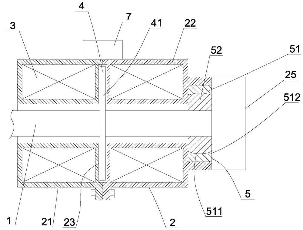
[0059] Embodiment 1: as figure 1 As shown, an assembled generator, which is suitable for the range extender of electric vehicles, specifically includes a motor housing 1, a rotor shaft 2 arranged in the motor housing, a junction box 7 for connecting input and output cables, a control 15, the rotor 4 and the stator winding 3 are sequentially arranged in the motor housing in the axial direction of the rotor shaft. They are sequentially arranged in series in the axial direction, so as to facilitate the user's assembly. The transfer box facilitates the electrical connection between the stator winding and the charger or other electrical equipment.

[0060] As those skilled in the art should know, the two ends of the rotor can form an end surface magnetic field, and the magnetic force lines output from one end and return to the other end. Therefore, when the rotor shaft is driven by the output shaft of the engine to rotate, and then drives the rotor to rotate, the rotor rotates re...

Embodiment 2

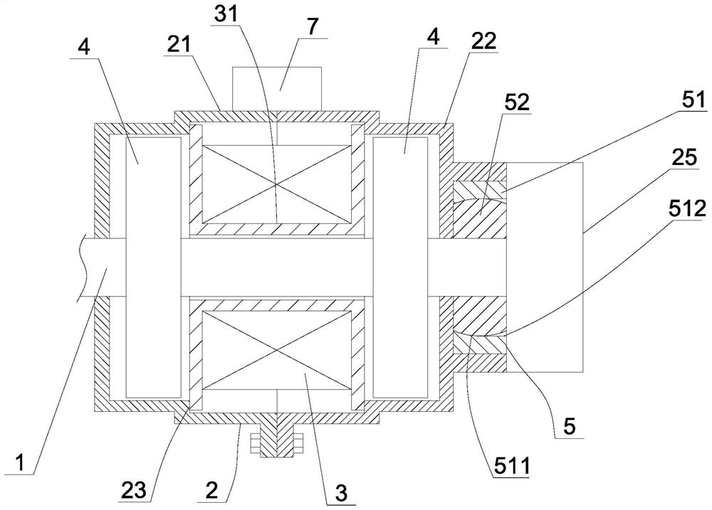
[0076] Embodiment 2: a kind of range extender, such as Figure 4 , Figure 5 As shown, it includes an engine 10 with an outer casing 101 and an output shaft 102, and a double-stator generator as described in Embodiment 1. The rotor shaft of the generator is connected to the output shaft of the engine, and the connection end of the motor casing is connected to the casing of the engine. body connected. Specifically, the assembly of the range extender includes the following steps:

[0077] a. Install the stator windings into the first housing and the second housing respectively, the stator windings are lower than the openings of the first housing and the second housing, so that at the openings of the first housing and the second housing Form a concave semi-installation cavity;

[0078] b. Connect the rotor shaft with the output shaft of the engine, and fix the connecting end of the first casing on the outer casing of the engine, and at this time, the rotor shaft passes through...

Embodiment 3

[0092] Embodiment 3: a kind of range extender, such as Figure 10 As shown, it includes an engine with an outer casing and an output shaft, and a dual-rotor generator as described in Embodiment 1. The output shaft of the engine is connected to the rotor shaft of the generator, and one end of the motor casing of the generator is connected to the outer casing of the engine. connect. When the engine is running, the output shaft can drive the rotor shaft to rotate, and then realize the power generation of the assembled generator, and the electricity generated by the assembled generator can charge the battery of the electric vehicle, so as to satisfy the driving of the electric vehicle. Specifically, the assembly of the range extender system includes the following steps:

[0093] a. Install the first mounting bracket with magnetic steel on the front side of the rotor shaft, and let the front end of the rotor shaft pass through the center hole of the first housing. At this time, th...


PUM


Abstract

The invention discloses an assembled generator and a range extender, the generator comprises a motor shell, a rotor shaft, a rotor and a stator winding arranged in the motor shell, and an adapter box, the rotor and the stator winding are arranged side by side in the axial direction, and the end part of the motor shell is provided with a first bearing for supporting the rotor shaft; the switching box comprises a current output end used for outputting current of the generator, and the controller comprises a control input end electrically connected with an output line of the generator and a control output end electrically connected with the current output end. The range extender comprises an engine, the generator and a controller, an output shaft of the engine is in transmission connection with a rotor shaft of the generator, and a motor shell of the generator is connected with an outer shell of the engine. Maintenance, disassembly and assembly in the use process are facilitated, the overall occupied space can be saved, meanwhile, the power of the generator can be conveniently adjusted according to the actual use requirement, and therefore the generated power of the generator can be matched with the actual electricity utilization requirement.

Description

technical field [0001] The invention relates to the technical field of generator manufacturing, in particular to an assembled generator and a range extender. Background technique [0002] With the improvement of people's awareness of environmental protection, electric vehicles using lithium batteries have begun to enter thousands of households. Due to the limitations of lithium battery technology and performance, there are still two main problems in electric vehicles: First, the cruising range of lithium batteries is limited. , Correspondingly, the charging time of lithium batteries is long, and fast charging cannot be achieved like refueling, and the number of suitable charging piles is limited, resulting in troublesome charging. The above technical problems limit the popularization of electric vehicles. For this reason, someone has invented a range extender suitable for electric vehicles. The existing range extender usually includes a generator, and the power of the genera...

Claims


Application Information

Patent Timeline
IPC IPC(8): H02K1/2796H02K1/30H02K5/22H02K11/30H02K16/02H02K3/28H02K3/50B60L50/62
CPCH02K1/2793H02K1/30H02K5/225H02K11/30H02K16/02H02K3/28H02K3/50B60L50/62Y02T10/70
Inventor 陈栋曹恩瑞陈云涛
Owner HANGZHOU ZONHOW ELECTRIC TECH CO LTD
Why Eureka
Try Eureka