
Energy-saving axial flow pump

A technology of axial flow pump and pump body, which is applied in the field of liquid conveying equipment, and can solve problems such as easy blockage at the input end of the pump body and influence on water flow

Pending Publication Date: 2022-06-07
YANGZHOU HONGYUE MECHANICAL CO LTD
View PDF7 Cites 0 Cited by
  • Summary
  • Abstract
  • Description
  • Claims
  • Application Information

AI Technical Summary

Problems solved by technology

[0002] As we all know, the energy-saving axial flow pump is a device that transports the liquid along the axial direction by the force generated by the blades of the rotating impeller on the liquid, and it has been widely used in the field of axial flow pump equipment; the existing energy-saving axial flow The pump includes a pump body, a cavity is arranged in the pump body, and an impeller assembly is arranged in the cavity; when the existing energy-saving axial flow pump is used, the pump body is installed in a suitable position, and the water is transferred from the bottom of the pump body during the rotation of the impeller assembly. to the cavity and output from the output end of the pump body; in the use of existing energy-saving axial flow pumps, it is found that when the equipment is used in diving, the position of the pump body is relatively fixed, and when the water environment is poor, the input end of the pump body is easier Blockage occurs, affecting the flow of water

Method used


Image

  • Energy-saving axial flow pump
  • Energy-saving axial flow pump
  • Energy-saving axial flow pump

Examples


Embodiment Construction

[0032] The technical solutions in the embodiments of the present invention will be clearly and completely described below with reference to the accompanying drawings in the embodiments of the present invention. Obviously, the described embodiments are only a part of the embodiments of the present invention, but not all of the embodiments. Based on the embodiments of the present invention, all other embodiments obtained by those of ordinary skill in the art without creative efforts shall fall within the protection scope of the present invention.

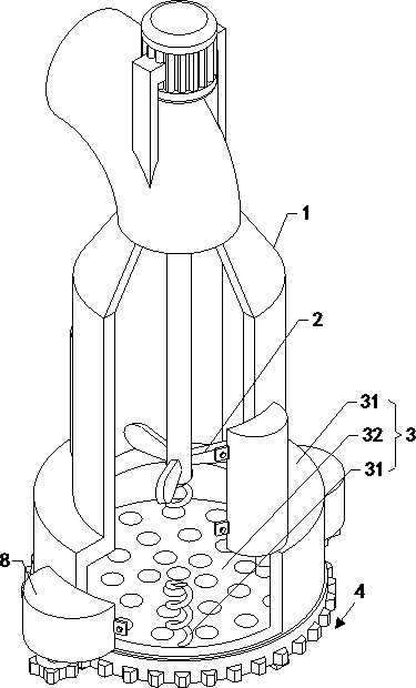
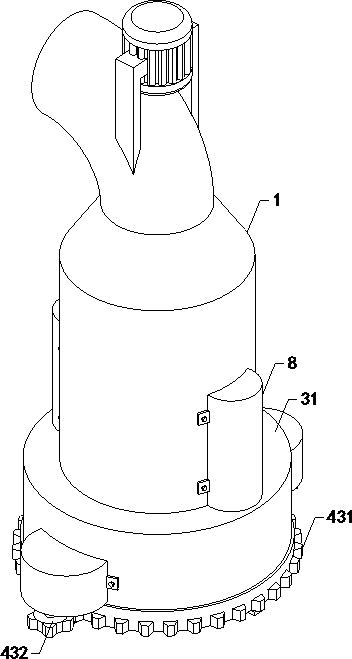
[0033] see Figure 1-6 , the embodiment of the present application provides an energy-saving axial flow pump, including a pump body 1, a cavity is arranged in the pump body 1, and an impeller assembly 2 is arranged in the cavity; it also includes:

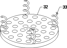
[0034] Filter device 3, the filter device 3 is arranged at the bottom end of the pump body 1, the filter device 3 includes a filter cartridge 31 fixedly arranged at the bottom end of the p...


PUM


Abstract

The invention relates to the technical field of liquid conveying equipment, in particular to an energy-saving axial flow pump which is additionally provided with a water filtering assembly, so that the phenomenon of water blockage is reduced, and the influence on water conveying is reduced. Comprising a pump body and further comprises a filtering device, the filtering device is arranged at the bottom end of the pump body and comprises a filtering cylinder fixedly arranged at the bottom end of the pump body, a filtering groove is formed in the bottom end of the filtering cylinder, a through hole is formed in the top end of the filtering cylinder, the output end of the through hole communicates with the bottom end of a cavity, a filtering plate is arranged in the filtering groove, and a buffering assembly is arranged at the top end of the filtering plate; the cleaning device is arranged at the bottom end of the filter cylinder, and the cleaning device comprises an X-shaped plate arranged on the lower side of the cleaning cylinder, a brush group fixedly arranged at the top end of the X-shaped plate and a driving assembly connected with the X-shaped plate.

Description

technical field [0001] The present invention relates to the technical field of liquid conveying equipment, in particular to an energy-saving axial flow pump. Background technique [0002] As we all know, the energy-saving axial flow pump is a device that relies on the force generated by the blades of the rotating impeller to transport the liquid along the axis direction. It has been widely used in the field of axial flow pump equipment; the existing energy-saving axial flow pump The pump includes a pump body, a cavity is arranged in the pump body, and an impeller assembly is arranged in the cavity; when the existing energy-saving axial flow pump is used, the pump body is installed in a suitable position, and the water is transmitted from the bottom end of the pump body during the rotation of the impeller assembly. into the cavity and output from the output end of the pump body; in the use of the existing energy-saving axial flow pump, it is found that when the equipment is u...

Claims


Application Information

Patent Timeline
Patent Type & Authority Applications(China)
IPC IPC(8): F04D3/00F04D29/70
CPCF04D3/00F04D29/708
Inventor 邰军虎吴桂璧陈修松
Owner YANGZHOU HONGYUE MECHANICAL CO LTD
Learn More