Movable electric vehicle charging pile for new energy electric vehicle
A technology of electric vehicles and charging piles, which is applied in the direction of electric vehicle charging technology, electric vehicles, charging stations, etc., can solve the problems of affecting the appearance of the city, the disorder of charging piles, and increasing the labor load of charging piles, so as to facilitate mobile replacement and reduce labor force Effect
- Summary
- Abstract
- Description
- Claims
- Application Information
AI Technical Summary
Problems solved by technology
Method used
Image
Examples
Embodiment 1
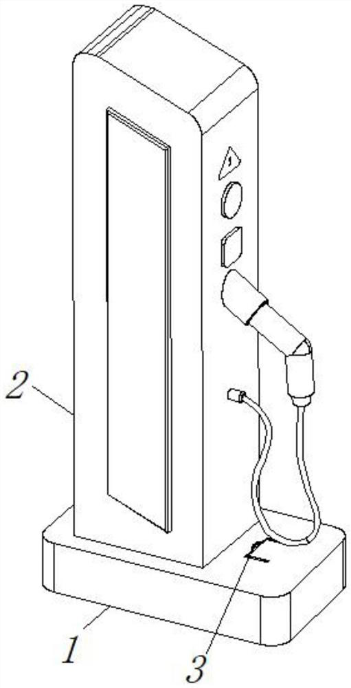
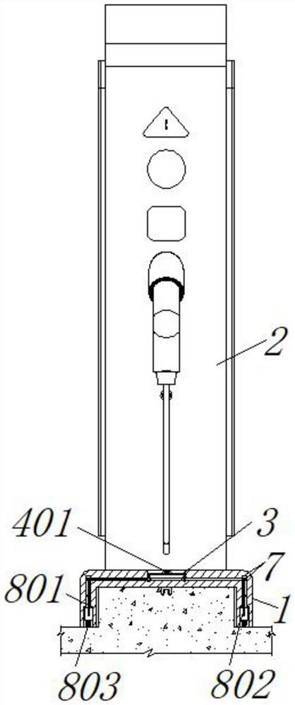
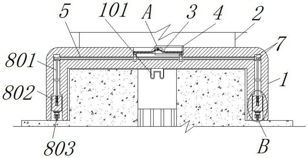
[0025] see figure 2 , image 3 and Figure 5 , the unlocking mechanism 4 includes an oil cavity 401 opened on the inner side of the handle of the driving rod 3, and a piston pressure rod 402 is engaged under the inner side of the oil cavity 401, a first spring 402a is installed on the outer side of the piston pressure rod 402, and the left and right inner sides of the driving rod 3 are both An oil passage 403 is opened, and a lock bar 404 is engaged with the inner right end of the oil passage 403. The middle of the driving rod 3 is designed in the shape of a handle. The lock bar 404 and the circular groove on the base 1 form a locking structure. When the position of the pile body 2 is moved and replaced, first manually hold the handle in the middle of the driving rod 3, and then use a single finger to cooperate with the first spring 402a to press the piston pressing rod 402, and the upward movement of the piston pressing rod 402 can effectively The oil inside the oil passag...
Embodiment 2
[0027] see Figure 2-6The difference from Embodiment 1 is that the moving mechanism 8 includes a reciprocating screw rod 801 welded under the inner side of the bevel gear set 7, and a slider 802 is threadedly connected to the outer side of the reciprocating screw rod 801, and the bottom of the slider 802 is welded with a bottom. Wheel 803, the bottom of the base 1 is connected with the wire plug 101 of the charging pile, the outer array of the drum 6 is articulated with a clip 601, and the end of the clip 601 is connected with a second spring 602, and the end of the second spring 602 is connected to the drum 6. In order to be fixed by welding, the inner ring array of the bevel gear set 7 is provided with a slot 701, and the slot 701 and the clip 601 form a one-way rotation structure. The driving rod 3 drives the driven rod 5 to reciprocate and flip, and the reciprocating flip of the driven rod 5 can drive the rotating drum 6, the clip 601 and the second spring 602 on the left ...
PUM
 Abstract
Description
Claims
Application Information
 - R&D
- Intellectual Property
- Life Sciences
- Materials
- Tech Scout
- Unparalleled Data Quality
- Higher Quality Content
- 60% Fewer Hallucinations
Browse by: Latest US Patents, China's latest patents, Technical Efficacy Thesaurus, Application Domain, Technology Topic, Popular Technical Reports.
© 2025 PatSnap. All rights reserved.Legal|Privacy policy|Modern Slavery Act Transparency Statement|Sitemap|About US| Contact US: help@patsnap.com


