Intelligent electric control pressure electromagnetic valve

A solenoid valve and electronic control technology, applied in the field of pressure solenoid valve, can solve the problems of solenoid valve damage, decrease in insulation performance, affecting the service life of solenoid valve, etc., and achieve the effect of reasonable structure and accuracy.

Pending Publication Date: 2022-06-03
三桥惠(佛山)新材料有限公司 +1
View PDF0 Cites 0 Cited by
  • Summary
  • Abstract
  • Description
  • Claims
  • Application Information

AI Technical Summary

Problems solved by technology

[0003] The insulation between the iron core and the winding wire of the existing solenoid valve is generally realized by enameled wire and insulating tape. The solenoid valve on the electric pressure cooker is easily invaded by water vapor, resulting in a decrease in insulation performance and affecting the service life of the solenoid valve.
Existing pressure solenoid valves are all independent components that need to be assembled multiple times, especially the solenoid valve uses tape insulation layer filling and winding process, the rupture and damage of the tape insulation layer during the assembly process will lead to damage to the solenoid valve
The existing pressure solenoid valve cannot adjust the pressure limit of the solenoid valve according to the pressure inside the electric pressure cooker, so that there is a safety problem in the use of the electric pressure cooker

Method used


Image

  • Intelligent electric control pressure electromagnetic valve
  • Intelligent electric control pressure electromagnetic valve
  • Intelligent electric control pressure electromagnetic valve

Examples


Embodiment Construction

[0023] The technical solutions of the present invention will be described below with reference to the accompanying drawings and embodiments.

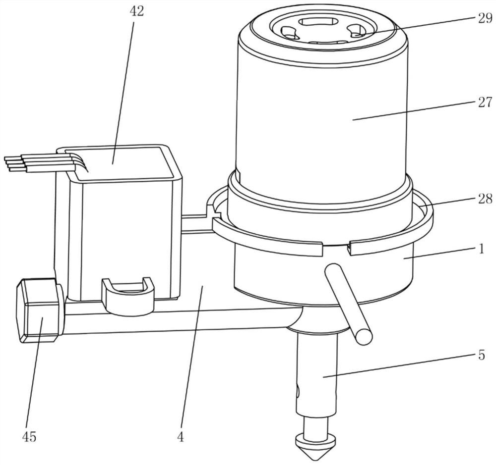
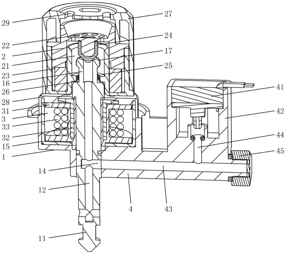
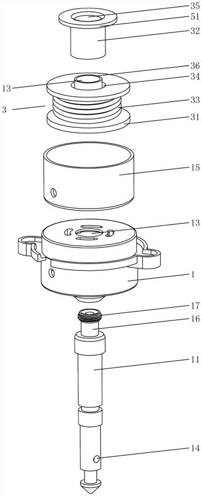
[0024] like Figure 1-5 As shown in the figure, an intelligent electronically controlled pressure solenoid valve according to the present invention includes a valve body 1, a gas valve stem 11 and a pressure cover 2, the valve body 1 is provided with a passage hole 13, and the gas valve stem 11 passes through the The passage hole 13 is fixedly connected with the valve body 1, and the gas valve rod 11 is provided with a pressure relief hole 12; the pressure cover 2 is movably mounted on the upper end of the gas valve rod 11, and the valve body 1 is provided with an electromagnetic assembly 3. The pressure cover 2 is provided with a permanent magnet 23; the lower end of the valve body 1 is provided with a pipe joint 4, one end of the pipe joint 4 is connected with the gas valve stem 11, and the pipe joint 4 is communicated with the pressu...


PUM


Abstract

The invention relates to the technical field of pressure electromagnetic valves, in particular to an intelligent electric control pressure electromagnetic valve. Comprising a valve body, an air valve rod and a pressure cover, a channel hole is formed in the valve body, the air valve rod penetrates through the channel hole, and a pressure relief hole is formed in the air valve rod; an electromagnetic assembly is arranged in the valve body, and a permanent magnet is arranged on the pressure cover; a pipe joint is arranged at the lower end of the valve body, the pipe joint is communicated with the pressure relief hole, and a pressure sensor is arranged on the pipe joint; the pressure sensor and the electromagnetic assembly are respectively connected with a main control board of the electric pressure cooker through leads; the pressure cooker is reasonable in structure, the sensing base is communicated with the pressure relief hole through the branch air channel on the pipe connector, the pressure sensor outputs a signal to the main control panel of the pressure cooker so that the current direction of the electromagnetic valve can be changed, and the electromagnetic assembly and the pressure cover are magnetically repelled and suspended to achieve intelligent pressure control and automatic pressure maintaining and relief. The pressure sensor monitors the internal pressure of the pressure cooker in real time, the main control board adjusts the current in the electromagnetic assembly in real time, and the accuracy of the set air pressure in the pressure cooker is guaranteed.

Description

technical field [0001] The invention relates to the technical field of pressure solenoid valves, in particular to an intelligent electronically controlled pressure solenoid valve. Background technique [0002] Existing cooking utensils such as electric pressure cookers use the principle that the magnetic valve and the electromagnetic sucker can generate both suction and repulsion to realize stepless adjustment of the pressure limit value of the electric pressure cooker. Its implementation is that when the electromagnetic chuck is not energized, the pressure-limiting pressure of the electric pressure cooker is determined by the suction force generated by the electromagnetic chuck and the magnetic valve; when the electromagnetic chuck is energized with direct current that increases from small to large, the electromagnetic chuck will generate adjacent to the magnetic valve. If the magnetic pole with the same surface is used, the repulsive force of the same magnetic pole will re...

Claims


Application Information

Patent Timeline
Patent Type & Authority Applications(China)
IPC IPC(8): F16K31/08F16K31/06F16K37/00F16K1/38F16K17/12A47J27/09A47J27/08
CPCF16K31/082F16K31/0655F16K31/0675F16K37/0091F16K1/38F16K17/12A47J27/09A47J27/0802
Inventor 龙克文
Owner 三桥惠(佛山)新材料有限公司
Why Eureka
Try Eureka