
Bearing structure, electric air compressor, dynamic balancing method and assembling method

An air compressor, electric technology, applied in the direction of machines/engines, liquid fuel engines, pump devices, etc., can solve the problems of impeller disassembly and reassembly, and achieve the effect of reducing wear

Pending Publication Date: 2022-06-03
ROBERT BOSCH GMBH
View PDF0 Cites 0 Cited by
  • Summary
  • Abstract
  • Description
  • Claims
  • Application Information

AI Technical Summary

Problems solved by technology

[0003] But there is the following problem here: after the dynamic balance, when assembling the whole EAC, since the bearing structure forming the thrust bearing together with the bearing part on the rotor shaft is between the impeller and the bearing part, it is necessary to replace the dynamically balanced The impeller of the rotor is disassembled, and then the bearing structure is placed on the rotor shaft between the impeller and the bearing part, and finally the impeller is assembled
However, the dynamic balance of the entire rotor will be greatly affected by disassembly and reassembly of the impeller

Method used


Image

  • Bearing structure, electric air compressor, dynamic balancing method and assembling method
  • Bearing structure, electric air compressor, dynamic balancing method and assembling method
  • Bearing structure, electric air compressor, dynamic balancing method and assembling method

Examples


Embodiment Construction

[0026] In order to make the technical problems, technical solutions and beneficial technical effects to be solved by the present invention clearer, the present invention will be further described in detail below with reference to the accompanying drawings and multiple exemplary embodiments. It should be understood that the specific embodiments described herein are only used to explain the present invention, rather than to limit the protection scope of the present invention.

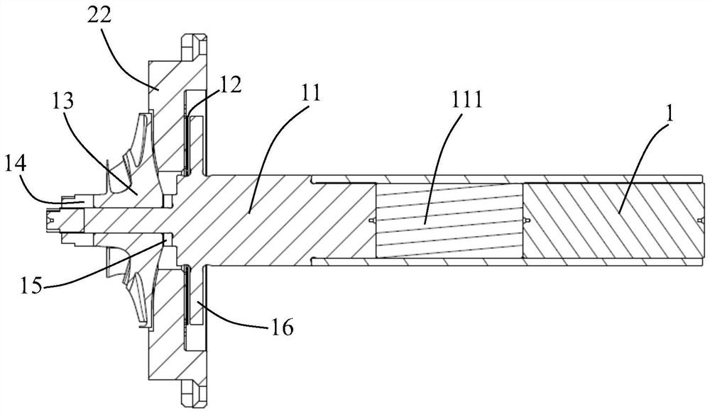
[0027] figure 1 An example of the rotor assembly 1 and bearing structure 22 of the EAC is shown. The rotor assembly 1 is for example rotatably supported in the housing of the EAC. The rotor assembly 1 includes a rotor shaft 11 and a bearing portion 12 provided on the rotor shaft 11 . A rotor 111 is provided in the rotor shaft 11 . The rotor 111 interacts, for example, with a not shown stator, which is arranged in the housing of the EAC. The bearing portion 12 is part of a thrust bearing for the rotor ...


PUM


Abstract

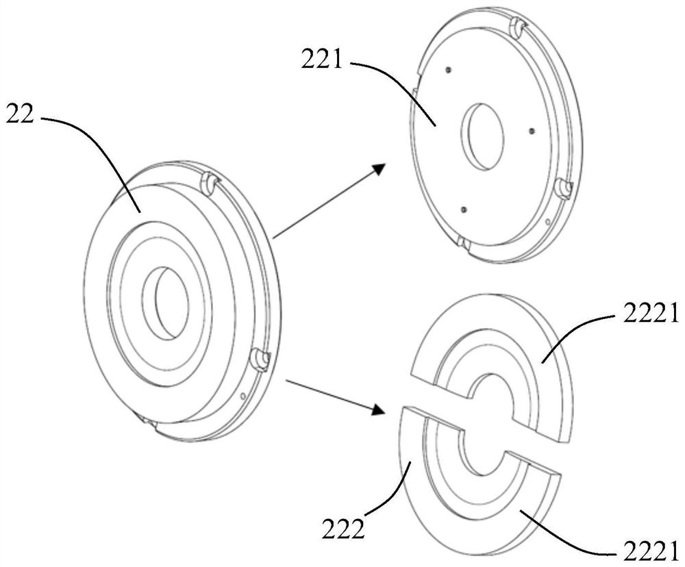
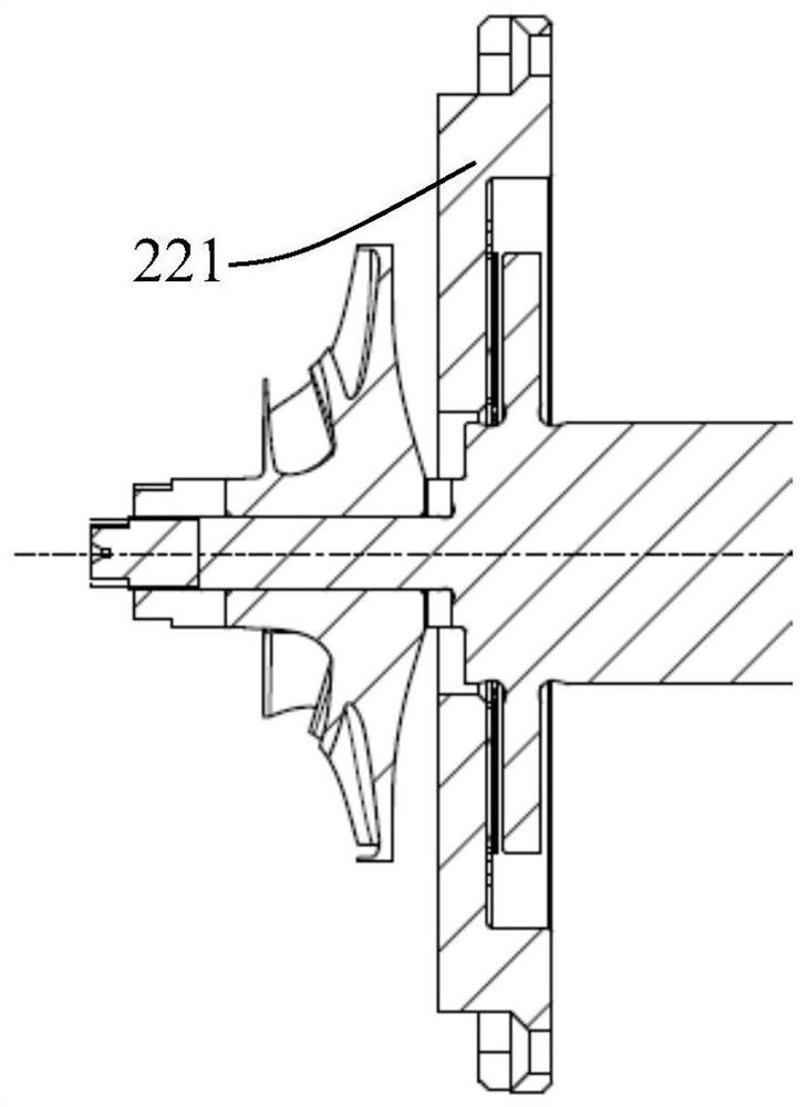
The invention relates to a bearing arrangement (22) for a rotor assembly (1) of an electric air compressor, the rotor assembly (1) comprising a rotor shaft (11) and a bearing portion (12) arranged on the rotor shaft (11), the bearing arrangement (22) together with the bearing portion (12) forming a thrust bearing, the bearing arrangement (22) comprising a first axial section (221) corresponding to the bearing portion (12) and a second axial section (222) axially adjacent to the first axial section (221), the second axial section (222) can be separated from the first axial section (221), and the second axial section (222) is configured to be assembled radially around the rotor shaft (11). The invention also relates to an electric air compressor, a dynamic balancing method and an assembling method. The invention has the advantages that the rotor assembly (1) does not need to be disassembled for mounting the bearing structure (22) after dynamic balancing, and the wear during dynamic balancing is reduced.

Description

technical field [0001] The invention relates to a bearing structure for a rotor assembly of an electric air compressor (EAC, electric air compressor), an electric air compressor including the bearing structure, and a dynamic balance for the rotor assembly of the electric air compressor and a method for assembling an electric air compressor. Background technique [0002] In EAC, the rotational speed of the rotor is very high (usually more than 100,000 rpm), so the rotor needs to be dynamically balanced. The rotor generally includes a rotor shaft and an impeller, wherein the impeller is usually fixed to the rotor shaft by means of washers and nuts. The rotor shaft and the impeller are each well balanced on a dynamic balancing machine. But as far as gaskets and nuts are concerned, even if efforts are made to improve the machining accuracy, the dynamic balance of the entire rotor will still fail to meet the requirements after assembly. Therefore, the entire rotor needs to be ...

Claims


Application Information

Patent Timeline
IPC IPC(8): F04D29/056F04D29/057F04D25/06F04D29/66F04D29/62F04D29/28
CPCF04D29/056F04D29/057F04D25/06F04D29/662F04D29/624F04D29/284F04D29/266
Inventor 王臣臣
Owner ROBERT BOSCH GMBH
Learn More