Heading machine cutter head and heading machine

A technology of cutter head and machine cutter, which is applied in mining equipment, tunnels, earth-moving drilling, etc., and can solve problems such as affecting construction progress.

Pending Publication Date: 2022-06-03
CHINA RAILWAY ENGINEERING EQUIPMENT GROUP CO LTD
View PDF5 Cites 1 Cited by
  • Summary
  • Abstract
  • Description
  • Claims
  • Application Information

AI Technical Summary

Problems solved by technology

[0005] The purpose of the present invention is to provide a roadheader cutter head to solve the technical problem that the roadheader cutter head in the prior art can achieve the purpose of crushing slag and preventing mud cake formation at the slag discharge port, but it will affect the construction progress; The object of the present invention is also to provide a roadheader using the above-mentioned roadheader cutter head

Method used


Image

  • Heading machine cutter head and heading machine
  • Heading machine cutter head and heading machine
  • Heading machine cutter head and heading machine

Examples


specific Embodiment 1

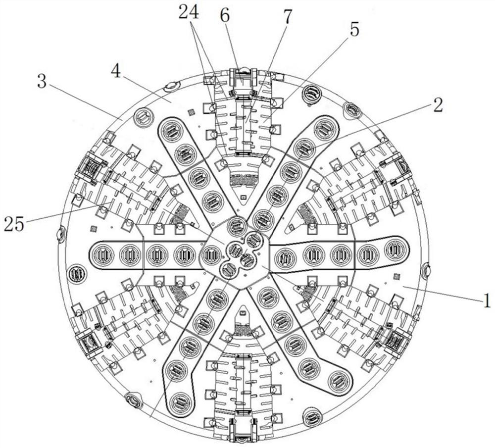
[0075] The roadheader provided in this embodiment includes a shield body, a main drive is arranged in the shield body, and a cutter head is arranged on the main drive. The structure of the cutter head is as follows: figure 1As shown, the cutter head includes a cutter head body 1 and a cutter 2 disposed on the cutter head body 1 . The cutter head body 1 includes a large ring 3 on the outside and a plurality of main beams 4 located in the large ring 3. The plurality of main beams 4 are radially distributed with the center of the cutter head main body 1 as the center, and are far from the center. One end is connected with the large ring 3 , and two adjacent main beams 4 cooperate with the large ring 3 to form a slag discharge port 5 , and some cutters 2 are arranged on each main beam 4 . During operation, the cutter head rotates under the drive of the main drive, excavating the face of the tunnel through cutter 2, and the excavated muck enters the soil bin on the rear side of the...

specific Embodiment 2

[0084] The specific embodiment 2 of the roadheader provided by the present invention is mainly different from the embodiment 1 in that: in the embodiment 1, the rotation axis of the soil stirring structure of the soil crushing device is arranged along the radial direction of the cutter head body. In the present embodiment, the rotation axis of the soil stirring structure of the soil crushing device is arranged in the slag discharge opening so as to intersect with the radial direction of the cutter head body.

specific Embodiment 3

[0085] The specific embodiment 3 of the roadheader provided by the present invention is mainly different from the embodiment 1 in that: in the embodiment 1, a grid and a soil crushing device are arranged at the slag discharge port to cooperate with the slag soil passing through the slag discharge port. Broken and refined. In this embodiment, the soil crushing device is only provided at the slag discharge port, and the stirring area of ​​the soil crushing device is increased in order to avoid the occurrence of a large soil crushing blind area.

[0086] The specific embodiment 4 of the roadheader provided by the present invention is mainly different from the embodiment 1 in that: in the embodiment 1, the grille is a blocking tooth structure. In this embodiment, the grid is a grid-like structure.


PUM


Abstract

The invention belongs to the field of tunnel excavation equipment, and particularly relates to a heading machine cutterhead and a heading machine. The heading machine comprises the cutterhead, the cutterhead comprises a cutterhead body, the cutterhead body is provided with a plurality of main beams, cutters are installed on the main beams, the main beams are arranged in the radial direction of the cutterhead body, and the main beams are distributed in a radial shape with the center of the cutterhead body as the center; a residue discharging opening allowing excavated residue soil to enter the rear side soil bin is formed in the space between every two adjacent main beams, a soil crushing device is arranged at each residue discharging opening and comprises a driving device and a soil stirring structure driven by the driving device to rotate so as to stir the residue soil, the driving devices are fixed to the cutterhead body, the soil stirring structures are located in the residue discharging openings, and the driving devices are fixed to the cutterhead body. The driving device drives the soil stirring structure to rotate so as to stir and crush the muck passing through the deslagging port, so that the muck is prevented from forming a mud cake at the deslagging port, and the tunneling machine achieves the purposes of crushing the muck and preventing the mud cake from forming at the deslagging port, and does not affect the construction progress.

Description

technical field [0001] The invention belongs to the field of tunnel excavation equipment, and particularly relates to a boring machine cutter head and a boring machine. Background technique [0002] With the development of science and technology, tunnel excavation using roadheaders has become the mainstream tunnel construction method at present. The frontmost component of the roadheader is the cutter head, and the continuous excavation of the soil layer is realized by the rotation and advancement of the cutter head. In order to ensure the continuous excavation, the excavated slag needs to be discharged backwards. Therefore, a slag discharge port will be opened on the cutter head of the roadheader. For example, the application publication number is CN112593952A, and the application publication date is April 2021. A pipe jacking machine cutter head disclosed by the Chinese invention patent application on the 2nd, the cutter head is provided with a soil discharge port (also cal...

Claims


Application Information

Patent Timeline
Patent Type & Authority Applications(China)
IPC IPC(8): E21D9/08
CPCE21D9/08
Inventor 李建斌闫阳张世伟贺开伟张琳代顺义黄士广马钢建白岩龙
Owner CHINA RAILWAY ENGINEERING EQUIPMENT GROUP CO LTD
Why Eureka
Try Eureka