Unpowered obstacle crossing snow sweeper

A snow removal vehicle and power technology, which is applied to snow surface cleaning, construction, cleaning methods, etc., can solve the problems of missing a large area of ​​snow by the snow pusher, the snow removal effect is not ideal, and the cleaning effect is reduced, and achieves a significant snow removal effect. Novel, quick installation effect

Pending Publication Date: 2022-06-03
WEIHAI GUANGTAI AIRPORT EQUIP CO LTD
View PDF0 Cites 0 Cited by
  • Summary
  • Abstract
  • Description
  • Claims
  • Application Information

AI Technical Summary

Problems solved by technology

The substantive deficiency of this structure is: although the snow pushing board is made up of a plurality of snow pushing boards, since the adjacent snow pushing boards are connected by shafts, when the snow pushing encounters a raised obstacle, a single pushing snow board The movement of the snowboard will drive the whole set of snow pushers to move through the shaft. Obviously, there will also be a phenomenon that the whole snow pusher misses a large area of ​​snow, and the snow removal effect is still not ideal.
1. When using a snow pusher to push snow, a small amount of sidestream snow will inevitably be generated. The traditional snow pusher has no side baffles on both sides. During snow removal operations, as the thickness of the snow increases, the snow will move to the pusher. If the outer side of the arc plate exceeds the width of the push plate, it will cause missing snow. If there is too much snow missing, a second cleaning is required, which greatly reduces the cleaning effect.

Method used


Image

  • Unpowered obstacle crossing snow sweeper
  • Unpowered obstacle crossing snow sweeper
  • Unpowered obstacle crossing snow sweeper

Examples


Embodiment Construction

[0046] The present invention will be described below with reference to the accompanying drawings and embodiments.

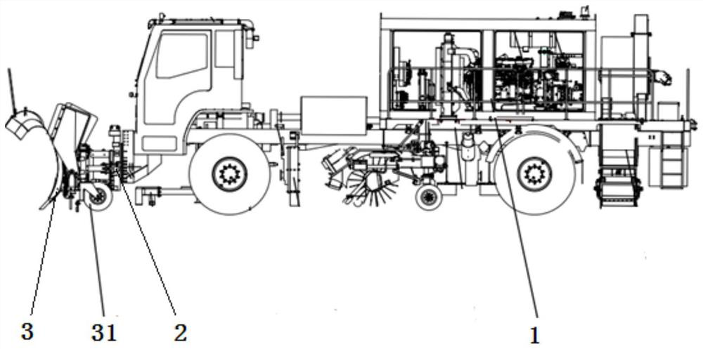
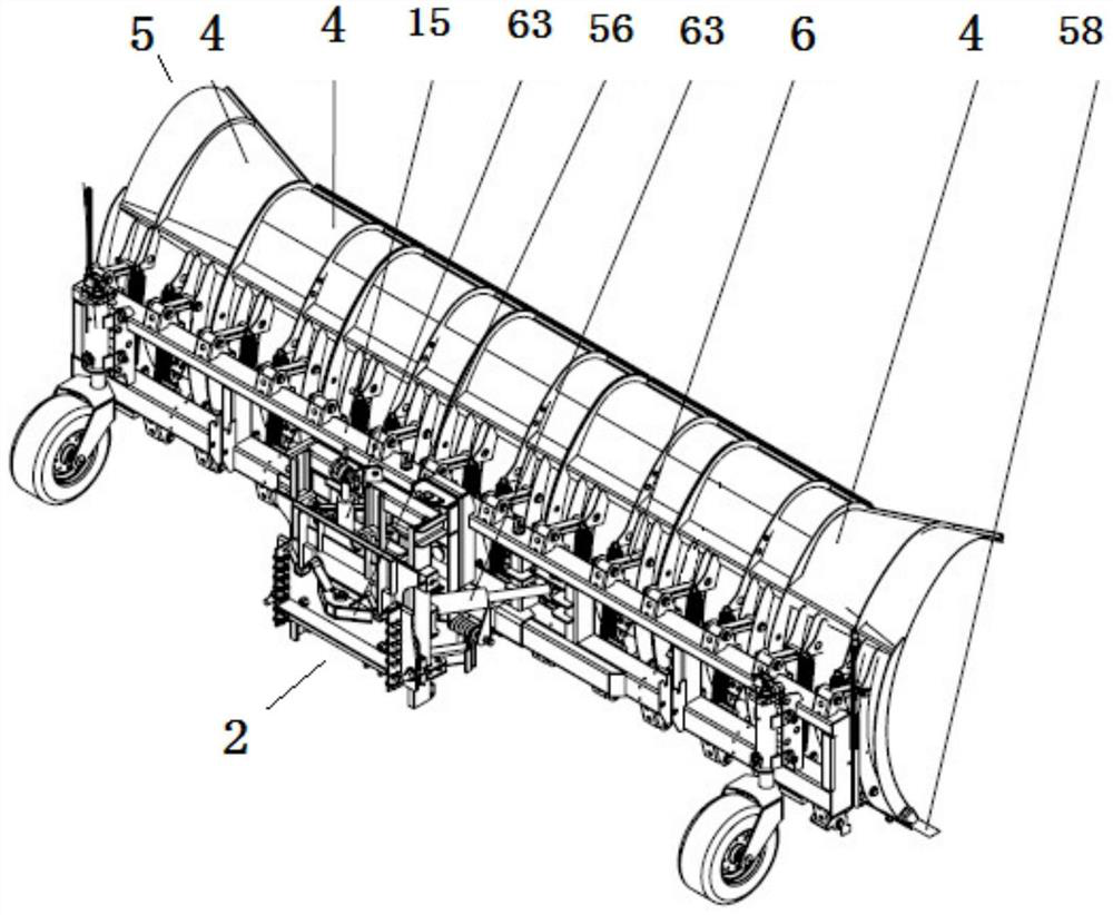
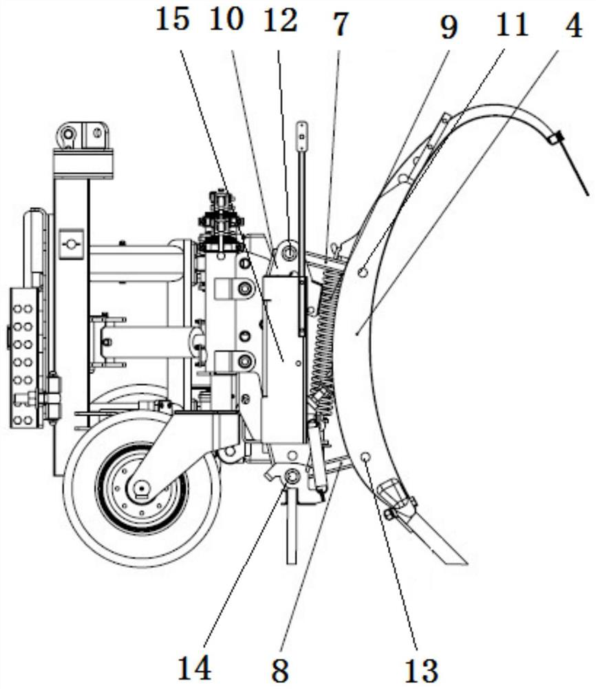
[0047] as attached figure 1 , figure 2 As shown in the figure, an unpowered obstacle-surmounting snow removal vehicle includes an automobile chassis 1, and the front end of the automobile chassis 1 is connected with a snow-pushing device 3 through a push-board support device 2, and is characterized in that the snow-pushing device 3 is composed of The snow pusher 5 composed of the unit snow pusher 4, the unit unpowered obstacle-crossing support device 6 and the main frame 15, which are arranged side by side, the side walls are in contact with each other and do not interfere with each other when moving, are composed of the unit snow pusher 4. Two juxtaposed units of unpowered obstacle crossing support devices 6 are connected with the main frame 15 to enhance the overall stability of the snowboard. When encountering a bump on the road, the unit snow pusher 4 corr...


PUM


Abstract

The unpowered obstacle crossing snow sweeper comprises an automobile chassis, and the front end of the automobile chassis is connected with a snow pushing plate device through a pushing plate supporting device. The device is characterized in that the snow pushing plate device is composed of a snow pushing plate, a unit unpowered obstacle crossing supporting device and a main frame, the snow pushing plate is composed of unit snow pushing plates, the unit snow pushing plates are arranged side by side, the side walls of the unit snow pushing plates make contact with one another, and the unit snow pushing plates do not interfere with one another during movement. When one of the unit snow pushing plates encounters a protrusion on the road surface, the unit snow pushing plate corresponding to the protrusion is blocked by the protrusion, so that the unit snow pushing plate generates upward and backward component force to push the unit unpowered obstacle crossing supporting device to deform and be rapidly lifted up to avoid an obstacle. When the unit unpowered obstacle crossing supporting device is used, the adjacent unit snow pushing plates continue to shovel accumulated snow on the ground without interference, after obstacle avoidance, the unit snow pushing plates rapidly return under the action of self gravity and self pulling force of the unit unpowered obstacle crossing supporting device, and the unit unpowered obstacle crossing supporting device has the advantages of being novel in structure, remarkable in snow removing effect, convenient to disassemble and assemble, high in working efficiency and the like.

Description

technical field [0001] The invention relates to the technical field of snow removal equipment, in particular to an unpowered obstacle-crossing snow removal vehicle with remarkable snow removal effect. Background technique [0002] As is known to all, the existing snow removal vehicle is usually equipped with a snow pushing device at the front end of the vehicle chassis. The snow pushing device is fixedly connected to the vehicle chassis through the snow pushing lifting and swinging device. During snow removal, the snow pushing device is used to remove the snow on the road. or dismissed. [0003] However, when actually pushing snow, due to the convexity of the road surface, such as manhole covers, it may cause impact on the snow pushing board, which may cause equipment damage in the lightest, and casualties of the driver in severe cases. Therefore, automatic obstacle-crossing snow pushing The device is in operation. [0004] After searching, CN2011102754137 discloses an inv...

Claims


Application Information

Patent Timeline
Patent Type & Authority Applications(China)
IPC IPC(8): E01H5/08
CPCE01H5/08
Inventor 唐明磊刘海涛戚洪涛陈林丛晓杰熊伟
Owner WEIHAI GUANGTAI AIRPORT EQUIP CO LTD
Why Eureka
Try Eureka