Two-step cutting method and jig for Mini BOX tube leg cutting

A technology of tube legs and fixtures, applied in the field of optical communication, can solve problems such as high risk and inability to carry out the mounting process, and achieve the effects of avoiding material loss, ensuring production capacity, and solving uniformity

Active Publication Date: 2022-06-03
辽宁优迅科技有限公司
View PDF11 Cites 0 Cited by
  • Summary
  • Abstract
  • Description
  • Claims
  • Application Information

AI Technical Summary

Problems solved by technology

[0003]At present, there is no such special fixture and reasonable cutting method, so the follow-up placement process cannot be carried out, and the risk is high

Method used


Image

  • Two-step cutting method and jig for Mini BOX tube leg cutting
  • Two-step cutting method and jig for Mini BOX tube leg cutting
  • Two-step cutting method and jig for Mini BOX tube leg cutting

Examples


Embodiment Construction

[0046] The specific embodiments provided by the present invention will be described in detail below with reference to the accompanying drawings.

[0047] A two-step cutting method for the cutting of Mini BOX tube legs, comprising the following steps:

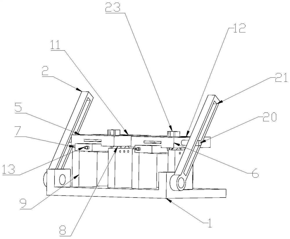
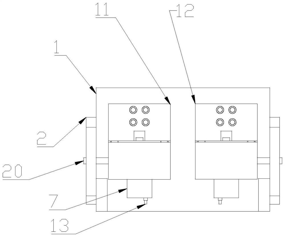
[0048] 1) Design a jig that can fix the Mini BOX and has a horizontal cutter head 3 and a vertical cutter head 4 for cutting;

[0049] 2) First, the vertical cutter head 4 completes the cutting on both sides of the Mini BOX tube leg side skirt 27 in the first step;

[0050] 3) Finally, use the horizontal cutter head 3 to complete the cutting of the bottom of the Mini BOX tube leg side skirt 27 in the second step.

[0051] like Figure 1-15 As shown in the figure, a jig for the cutting of Mini BOX tube legs, including a base 1, a grip rod 2, a horizontal cutter head tube seat placement table 11, a vertical cutter head tube seat placement table 12, a horizontal cutter head moving table 5, a horizontal cutter head cutter head 3, v...


PUM


Abstract

The invention provides a two-step type cutting method and jig for cutting Mini BOX tube legs, and the method comprises the following steps: designing a jig which can fix Mini BOX and is provided with a horizontal tool bit and a vertical tool bit for cutting; the method comprises the following steps: firstly, cutting two sides of a MiniBOX tube leg side skirt in the first step by a vertical tool bit; and (3) finally, a horizontal tool bit is used for cutting the bottom of the side skirt of the MiniBOX pipe leg. The simple mechanical structure design is utilized through two-step cutting, operation is easy, the time for installing and fixing the pipe base can be greatly shortened, and an operator can conveniently and rapidly complete installation and fixing of the pipe base. Therefore, smooth production is greatly guaranteed, productivity is guaranteed, cost is saved, and material loss is avoided.

Description

technical field [0001] The invention relates to the technical field of optical communication, in particular to a two-step cutting method and a jig for cutting a Mini BOX tube leg. Background technique [0002] In the production process of Mini BOX products, it is necessary to cut off the redundant pipe legs, and the styles of the pipe legs are different according to different processes. It needs to be cut in two steps. After the first step, other operations are performed. After the other operations are completed, the second step is performed to cut the excess tube legs. And the Mini BOX tube legs are crowned, which greatly deepens the difficulty factor. It is impossible to achieve uniform specifications and mass production with ordinary cutting tools. A solution to this problem is imminent. Now there is an urgent need for special fixtures to quickly and easily complete the cutting work. [0003] At present, there is no such special jig and reasonable cutting method, so t...

Claims


Application Information

Patent Timeline
IPC IPC(8): B21F11/00
CPCB21F11/00Y02P40/57
Inventor 周彪黄芙蓉郭萍黄兆波李浩凡
Owner 辽宁优迅科技有限公司
Why Eureka
Try Eureka