


Quick Research
Generate reliable direction feasibility study reports for your R&D in just a few steps.

Technical Q&A
Discover and master advanced knowledge NOW. Basics, ideas, possibilities, all at once.

Find Solutions
As an expert in R&D theories, this can generate solutions to your technical problems instantly.

Evaluate Feasibility
Analyze your overall solution with one click, know your potential R&D risks in advance.

Monitor Landscape
Get weekly tech updates, stay abreast of the latest tech innovations and key insights.
Efficient test tube oscillation device for hospital clinical laboratory
A laboratory and test tube technology, which is applied in the field of high-efficiency test tube vibration devices used in hospital laboratory departments, can solve the problems of hand soreness, slow test speed, and slow response.
- Summary
- Abstract
- Description
- Claims
- Application Information
AI Technical Summary
Problems solved by technology
Method used
Image


Examples
Embodiment 1
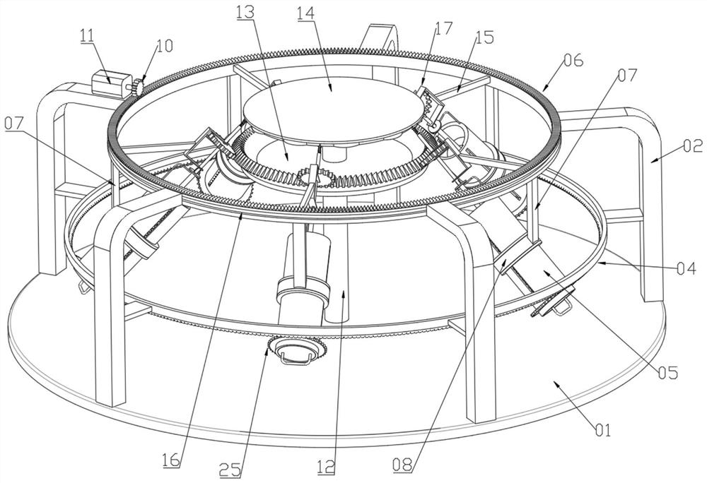
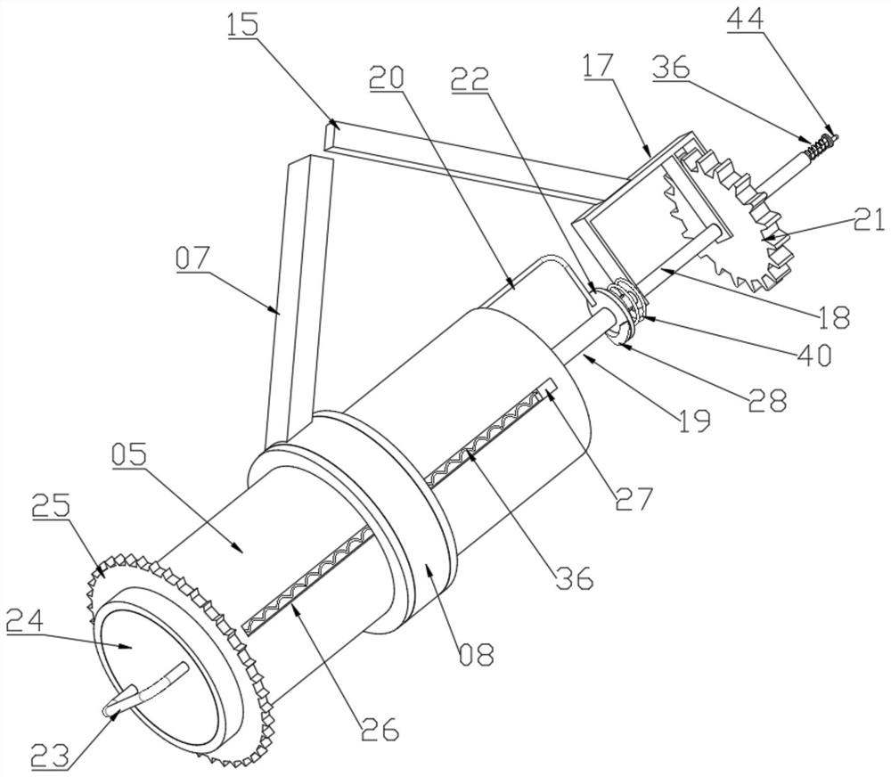
[0024] see Figure 1 to Figure 7 , a high-efficiency vibration device for test tubes used in a hospital laboratory, including a support foot 02 fixedly connected to the bottom plate 01, an external vibration module is arranged on the support foot 02, and the external vibration module includes a limit sliding connection on the support foot 02 A toothed ring 06. A boom 07 is fixedly connected to the gear ring 06, a swivel 08 is fixedly connected to the boom 1 07, an oscillation tube 05 is rotatably connected to the upper limit of the swivel 08, and a clamp 35 is connected to the inner limit sliding of the oscillation tube 05. , the lower end of the clamping seat 35 is fixedly connected with the chassis 24, the support foot 02 is fixedly connected with a bevel gear ring 04 through a fixing plate, the outer wall of the oscillation tube 05 is fixedly connected with a gear ring 25 meshing with the bevel gear ring 04, the support foot 02 There is also a driving device for driving the...
Embodiment 2
[0043] see Figure 8 , as another embodiment of the shaking mechanism, the shaking mechanism includes a spring 41 fixedly connected to one end of the oscillating tube 05 close to the spline shaft 18, the shaking rod 19 is fixedly connected with a shaking piece 42, and the shaking piece 42 is fixedly connected with a convex Block 43 , the vibrating plate 42 is pressed against the mounting frame 17 through the third spring 41 .
[0044] When the vibrating rod 19 rotates, it will drive the vibrating plate 42 to rotate at the same time. Whenever the bump 43 on the vibrating plate 42 rotates to the position of the mounting frame 17, the mounting frame 17 will push the bump 43 to push the vibrating plate 42 towards the vibrating tube 05. It moves in the direction of movement, and then resets by the spring three 41, so that the oscillating rod 19 can make the oscillating blade 29 perform reciprocating motion, so that the oscillating blade 29 can perform vertical and oscillating effec...
PUM
 Abstract
Description
Claims
Application Information
 - R&D Engineer
- R&D Manager
- IP Professional
- Industry Leading Data Capabilities
- Powerful AI technology
- Patent DNA Extraction
Browse by: Latest US Patents, China's latest patents, Technical Efficacy Thesaurus, Application Domain, Technology Topic, Popular Technical Reports.
© 2024 PatSnap. All rights reserved.Legal|Privacy policy|Modern Slavery Act Transparency Statement|Sitemap|About US| Contact US: help@patsnap.com