Chemical tail gas treatment device and method capable of avoiding blockage and achieving automatic cleaning

A chemical tail gas treatment and automatic cleaning technology, applied in chemical instruments and methods, separation methods, transportation and packaging, etc., can solve the problems of slowing down of tail gas outflow, damage of tail gas treatment devices, and increase of air pressure, so as to avoid outgassing The effect of speed reduction, avoiding the deterioration of gas circulation, and avoiding the slowdown of efficiency

Inactive Publication Date: 2022-06-03
沈菊敏
View PDF0 Cites 2 Cited by
  • Summary
  • Abstract
  • Description
  • Claims
  • Application Information

AI Technical Summary

Problems solved by technology

[0003] In the prior art, during the treatment process of chemical tail gas, since the chemical tail gas will be accompanied by some chemical particles, the continuous accumulation and blockage of chemical particles will slow down the flow rate of chemical tail gas, affect the treatment efficiency of chemical tail gas, and slow down the flow of tail gas. The inflow speed of the exhaust gas will inevitably lead to the continuous increase of the internal pressure and damage the exhaust gas treatment device.
[0004] Therefore, the demand for high-reliability products is imminent, so we propose a chemical tail gas treatment device and method that avoids clogging and automatically cleans, which has the functions of preventing the internal pressure from continuously increasing and causing damage to the processing device and automatic processing to prevent clogging from affecting chemical tail gas treatment. efficiency

Method used


Image

  • Chemical tail gas treatment device and method capable of avoiding blockage and achieving automatic cleaning
  • Chemical tail gas treatment device and method capable of avoiding blockage and achieving automatic cleaning
  • Chemical tail gas treatment device and method capable of avoiding blockage and achieving automatic cleaning

Examples


Embodiment Construction

[0030] The technical solutions in the embodiments of the present invention will be clearly and completely described below with reference to the accompanying drawings in the embodiments of the present invention. Obviously, the described embodiments are only a part of the embodiments of the present invention, but not all of the embodiments. Based on the embodiments of the present invention, all other embodiments obtained by those of ordinary skill in the art without creative efforts shall fall within the protection scope of the present invention.

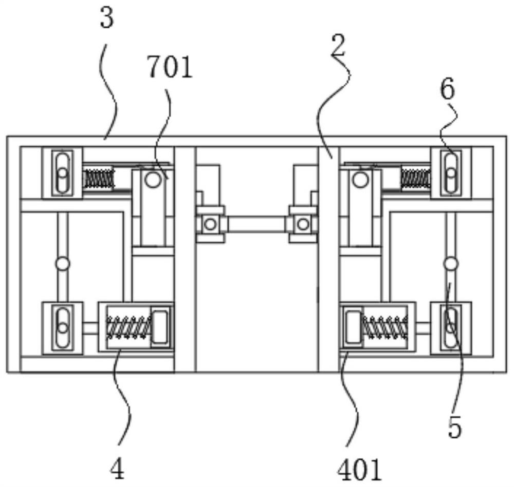
[0031] see Figure 1-6 , a chemical exhaust gas treatment device that avoids clogging and automatically cleans, including a treatment tank 1, the top of the treatment tank 1 is fixedly connected with a casing 3, the inner wall of the casing 3 is fixedly connected with a pipeline 2, and the left and right sides of the pipeline 2 are fixedly connected. There is an expansion assembly 4 , and the expansion assembly 4 includes an expansion...


PUM


Abstract

The invention relates to the technical field of waste gas treatment, and provides a chemical tail gas treatment device capable of avoiding blockage and achieving automatic cleaning, the chemical tail gas treatment device comprises a treatment tank, the top of the treatment tank is fixedly connected with a shell, the inner wall of the shell is fixedly connected with a pipeline, and the left side and the right side of the pipeline are fixedly connected with expansion assemblies; the inner wall of the expansion assembly is movably connected with a lever. According to the chemical tail gas treatment device and method capable of avoiding blockage and achieving automatic cleaning, firstly, tail gas is conveyed through a pipeline, chemical particles existing in the tail gas can be attached to the outer wall of a filter plate along with the tail gas passing through the filter plate, the air permeability of the filter plate is reduced, and the air pressure in the pipeline is increased along with the fact that the tail gas continuously enters the pipeline; the piston is extruded by air pressure, and the piston compresses the compression spring to increase the volume in the pipeline, so that the air pressure in the pipeline is reduced, air circulation is prevented from becoming poor, and the pipeline is extruded by the air pressure.

Description

technical field [0001] The invention relates to the technical field of waste gas treatment, in particular to a chemical tail gas treatment device and method for preventing clogging and automatically cleaning. Background technique [0002] Chemical industry refers to the production and development of chemical industry. Chemical industry is an indispensable and important part of the national economy. Chemical industry production will inevitably produce chemical exhaust gas, which seriously pollutes the environment. Therefore, it is necessary to purify chemical exhaust gas to protect the environment. . [0003] In the prior art, in the process of chemical exhaust gas treatment, because the chemical exhaust gas will be accompanied by some chemical particles, the continuous accumulation and blockage of the chemical particles will slow down the flow speed of the chemical exhaust gas, affect the treatment efficiency of the chemical exhaust gas, and the exhaust gas flow rate will be...

Claims


Application Information

Patent Timeline
Patent Type & Authority Applications(China)
IPC IPC(8): B01D46/10B01D46/681
CPCB01D46/10
Inventor 沈菊敏
Owner 沈菊敏
Why Eureka
Try Eureka