Eureka AIR delivers breakthrough ideas for toughest innovation challenges, trusted by R&D personnel around the world.

A metal material ring welding machine

A circular welding and metal material technology, which is applied in the direction of welding equipment, metal processing equipment, auxiliary welding equipment, etc., can solve the problems of keeping the width of the weld seam unchanged, adverse effects of welding effects, and effects of welding effects, etc., to achieve improved welding The effect of uniform distribution of welding holes and the effect of improving applicability

Active Publication Date: 2022-07-05
南通苏鲁达智能制造科技有限公司
View PDF0 Cites 0 Cited by
  • Summary
  • Abstract
  • Description
  • Claims
  • Application Information

AI Technical Summary

Problems solved by technology

[0003] At present, the welding of metal pipes is mainly operated by hand-held welding torches. This method has the following problems: (1), during the welding process of metal pipes, it is difficult to ensure that the width of the weld between the end faces of the two metal pipes remains unchanged. , so that the welding effect is affected; (2), in order to reduce welding deformation and reserve welding deformation space, it is usually necessary to reserve welding holes evenly in the circular weld, that is, commonly known as flower welding, and manually hold the welding torch to weld When welding, the welding effect is poor and it is difficult to ensure that the reserved welding holes are evenly distributed, which will also adversely affect the welding effect

Method used


Image

  • A metal material ring welding machine
  • A metal material ring welding machine
  • A metal material ring welding machine

Examples


Embodiment Construction

[0030] Embodiments of the present invention are described in detail below with reference to the accompanying drawings, but the present invention can be implemented in many different ways as defined and covered by the claims.

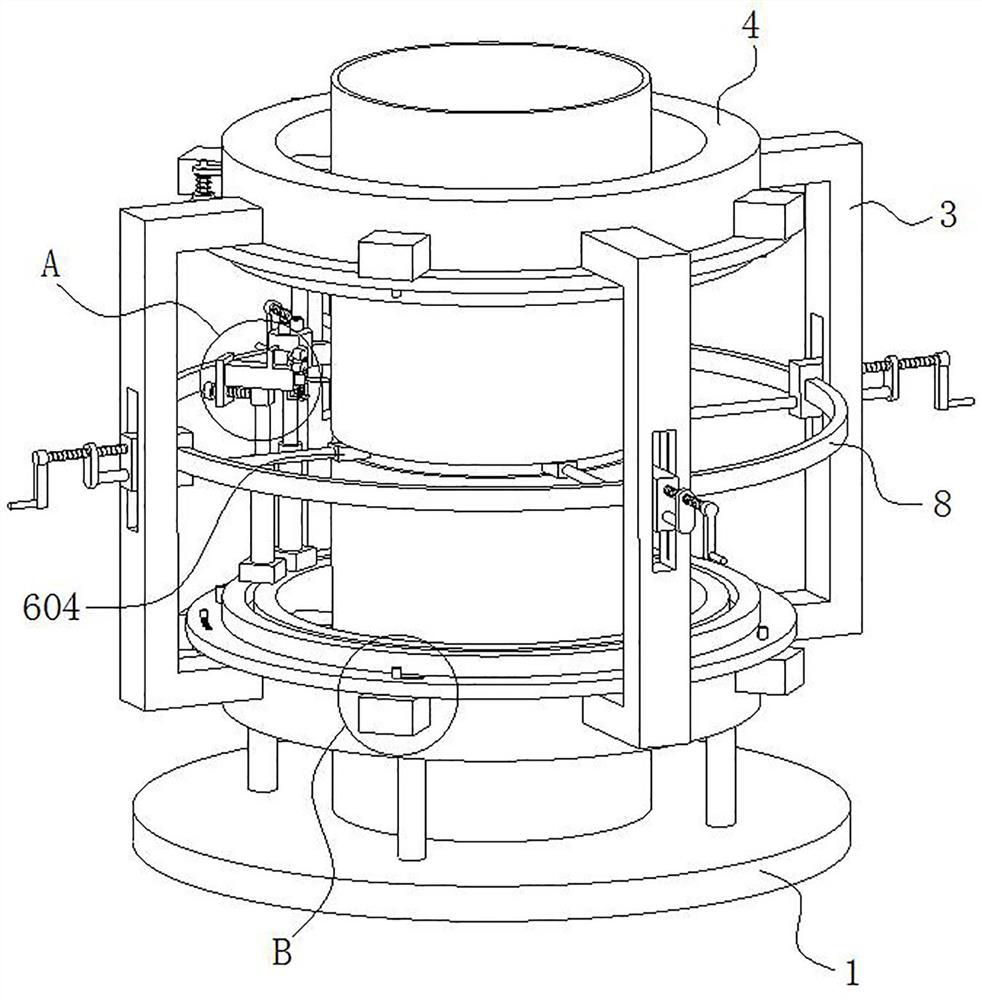
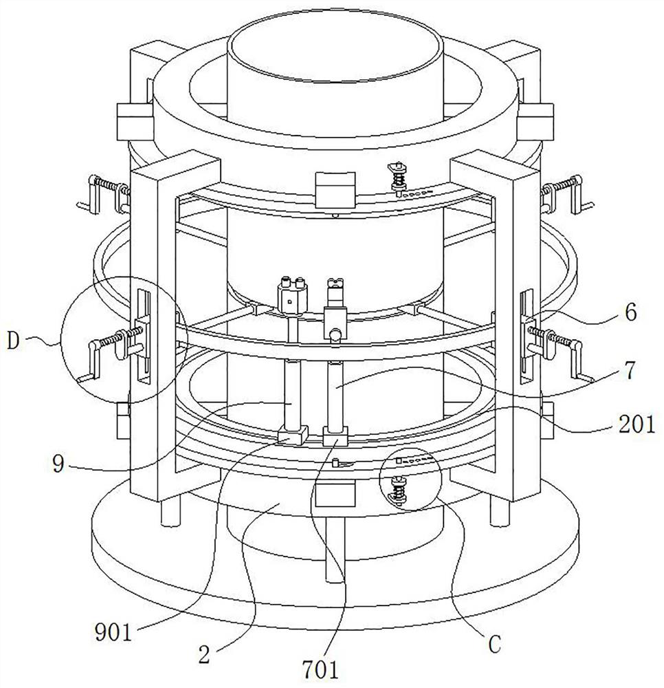
[0031] like figure 1 and figure 2 As shown, this embodiment provides a metal material annular welding machine, including a horizontal base 1, a horizontal first annular seat 2 is fixedly installed above the base 1 through a support column, and the outer side wall of the first annular seat 2 is along its circumference. A plurality of concave-shaped seats 3 are uniformly and fixedly installed, and a second annular seat 4 located above the first annular seat 2 and coinciding with the axis of the first annular seat 2 is fixedly installed among the plurality of concave-shaped seats 3 .

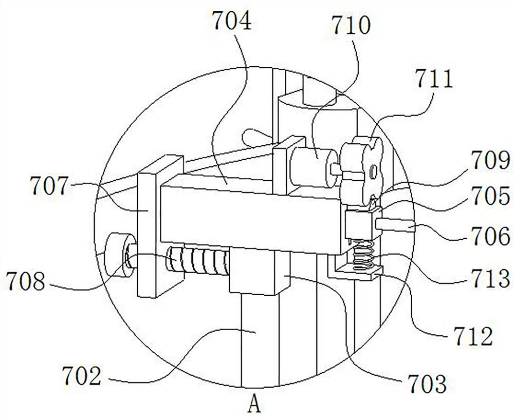
[0032] like figure 1 , Figure 4 , Figure 5 and Figure 7 As shown, a positioning mechanism 5 is installed on both the first annular seat 2 and the second annular seat...


PUM


Abstract

The invention belongs to the technical field of welding, in particular to a metal material annular welding machine, comprising a horizontal base, a horizontal first annular seat is fixedly installed above the base through a support column, and the outer side wall of the first annular seat is uniformly fixed along its circumferential direction A number of recessed seats are installed, and a second ring seat located above the first ring seat and coinciding with the axis of the first ring seat is fixedly installed between the several recessed seats; both the first ring seat and the second ring seat are installed There is a positioning mechanism, a support mechanism is installed on the concave-shaped seat, and a welding mechanism is slidably installed on the upper surface of the first annular seat; the invention ensures that the welding seam width between the end faces of the two metal pipes remains unchanged during the welding process, ensuring the The reserved welding holes are evenly distributed, thereby improving the welding effect.

Description

technical field [0001] The invention belongs to the technical field of welding, in particular to a metal material annular welding machine. Background technique [0002] The metal materials are usually connected by welding. When welding two metal pipes, the ends of the two metal pipes need to be close to each other, and a welding seam is reserved between the two metal pipes to make the two metal pipes. The axes are coincident, and then the welding rod attached to the welding seam is welded into the welding seam using the welding torch. [0003] At present, the welding of metal pipes is mainly performed by manual hand-held welding torches. This method has the following problems: (1) In the process of welding metal pipes, it is difficult to ensure that the width of the weld between the end faces of two metal pipes remains unchanged. , which will affect the welding effect; (2) In order to reduce welding deformation and reserve welding deformation space, it is usually necessary ...

Claims


Application Information

Patent Timeline
Patent Type & Authority Patents(China)
IPC IPC(8): B23K37/00B23K37/053B23K37/02
CPCB23K37/00B23K37/053B23K37/02
Inventor 季东霞杨锋陈培培方丽
Owner 南通苏鲁达智能制造科技有限公司
Why Eureka
Eureka Blog
Learn More