Vagina cleaning equipment suitable for nursing in obstetrics and gynecology department
A cleaning equipment, obstetrics and gynecology technology, applied in the direction of sanitary equipment for toilets, medical science, medical equipment, etc., can solve the problems of increasing the work intensity of medical staff, inconvenient support, inconvenient to carry, etc., to achieve convenient fixation Cleaning head device, soft and elastic texture, good effect
- Summary
- Abstract
- Description
- Claims
- Application Information
AI Technical Summary
Problems solved by technology
Method used
Image
Examples
Embodiment 1
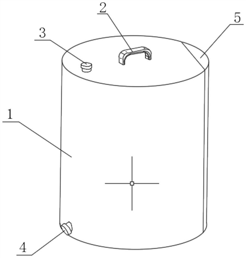
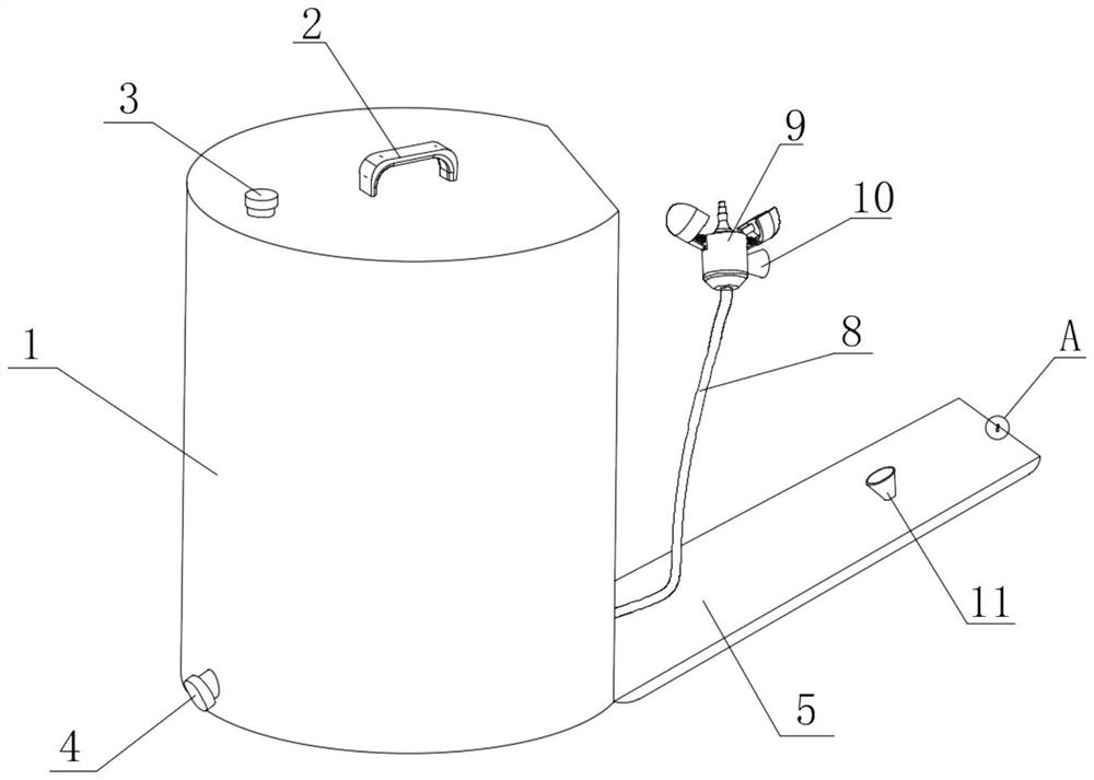
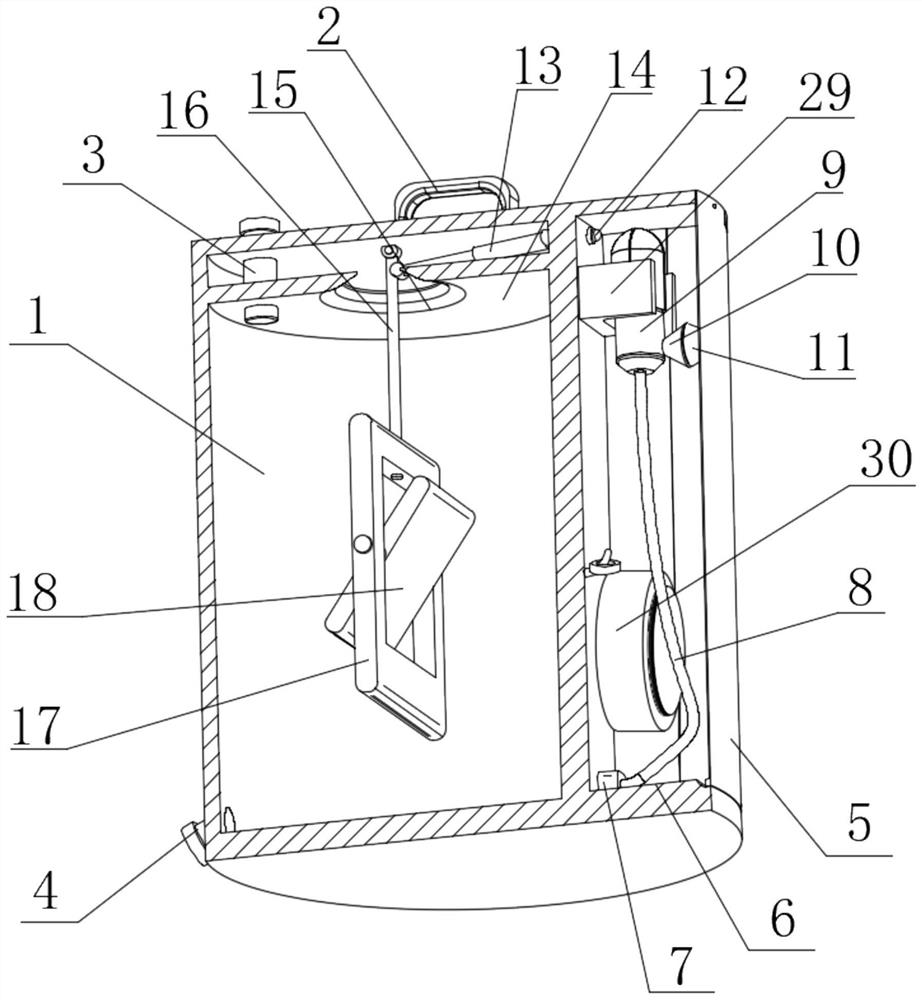
[0037] see Figure 1-Figure 4 and 7- Figure 10 , the present invention provides a technical solution: a vaginal cleaning device suitable for obstetrics and gynecology nursing, comprising a device body 1, a handle 2 is fixedly connected to the top center of the device body 1, and a water-filling device is arranged on the top of the device body 1 Device 3, one side of the device body 1 is fixedly connected with a water outlet device 4, the side of the device body 1 away from the water outlet device 4 is provided with a side groove 6, and the bottom inner wall of the side groove 6 is hinged with a flap 5. The size is adapted to the size of the side slot 6, wherein the flap 5 is tightly attached to the device body 1 when it is turned over, so that the flap 5 blocks the side slot 6, and the bottom inner wall of the side slot 6 is fixedly connected with a small suction cup. One side of the water pump 7, the small suction pump 7 is fixedly connected with a water pipe 8, the side of...
Embodiment 2
[0042] see Figure 1-Figure 6 As shown, on the basis of the first embodiment, the present invention provides a technical solution: a slot 19 is opened on the side of the device body 1 close to the flap 5, a through slot 20 is opened inside the flap 5, and the flap 5 is close to One side of the through slot 20 is provided with a through hole 21, and the interior of the flip plate 5 is provided with a moving rod 22 that is adapted to the through hole 21. One side of the moving rod 22 is fixedly connected with an insertion rod 23, and the other side of the moving rod 22 is provided. One side is fixedly connected with a moving block 27, and one side of the moving block 27 is attached to one side of the outer wall of the flap 5, wherein, after the moving block 27 is attached to the outer wall of the flap 5, it is convenient and stable to place, not easy to shift, move The outer wall of the rod 22 is sleeved with a return spring 28, and the return spring 28 is located inside the thr...
Embodiment 3
[0045] see Figure 1-Figure 4 As shown, on the basis of Embodiment 1 and Embodiment 2, the present invention provides a technical solution: a hydraulic switch 12 is fixedly connected to one inner wall of the side groove 6, and a hydraulic rod 13 is hinged to the inner wall of the top of the equipment body 1, A baffle 14 is fixedly connected to the inner wall of one side of the equipment body 1 and is located below the hydraulic rod 13 . The baffle 14 is provided with a conical hole 15 inside, and the hinge rod 16 penetrates through the inside of the conical hole 15 , wherein the conical hole 15 The setting is to supply the movable space of the hinge rod 16, the top inner wall of the equipment body 1 is hinged with the hinge rod 16, the side of the hydraulic rod 13 away from the equipment body 1 is hinged with the outer wall of the hinge rod 16, wherein the hydraulic rod 13 is telescopic When the hinge rod 16 is hinged with it, it is easy to rotate, the bottom of the hinge rod ...
PUM
 Abstract
Description
Claims
Application Information
 - R&D Engineer
- R&D Manager
- IP Professional
- Industry Leading Data Capabilities
- Powerful AI technology
- Patent DNA Extraction
Browse by: Latest US Patents, China's latest patents, Technical Efficacy Thesaurus, Application Domain, Technology Topic, Popular Technical Reports.
© 2024 PatSnap. All rights reserved.Legal|Privacy policy|Modern Slavery Act Transparency Statement|Sitemap|About US| Contact US: help@patsnap.com


