Network switch with anti-electromagnetic interference function

A network switch and anti-electromagnetic interference technology, which is applied in the field of network switches, can solve the problems of short service life, interference with the normal operation of the network switch, and easy influence of the normal operation of the network switch, and achieve the effect of avoiding illegal disassembly

Inactive Publication Date: 2022-05-27
深圳鼎盛时代科技有限公司
View PDF0 Cites 0 Cited by
  • Summary
  • Abstract
  • Description
  • Claims
  • Application Information

AI Technical Summary

Problems solved by technology

[0003] The existing network switches mainly have the following technical defects: First, the traditional network switch mainly blocks the interference of external electromagnetic waves on the work of the network switch through the outer shell, but the outer shell is mainly produced by assembling the main shell and the bottom plate, and then the shell There is a gap between the inside and the outside of the body, so that the external electromagnetic wave enters from the gap and interferes with the normal operation of the network switch, thus causing the problem that the external electromagnetic wave cannot be completely blocked, and the normal operation of the network switch is easily affected; second, the traditional network switch uses cooling holes And the cooling fan to dissipate heat inside, but the fan generates wind to dissipate heat, which has the disadvantages of high noise and poor cooling effect. At the same time, the wind blows easily brings dust from the outside into the inside of the network switch, resulting in a large amount of dust inside the network switch over a long period of time. Accumulation, thus causing the problem of short service life

Method used


Image

  • Network switch with anti-electromagnetic interference function
  • Network switch with anti-electromagnetic interference function
  • Network switch with anti-electromagnetic interference function

Examples


Embodiment

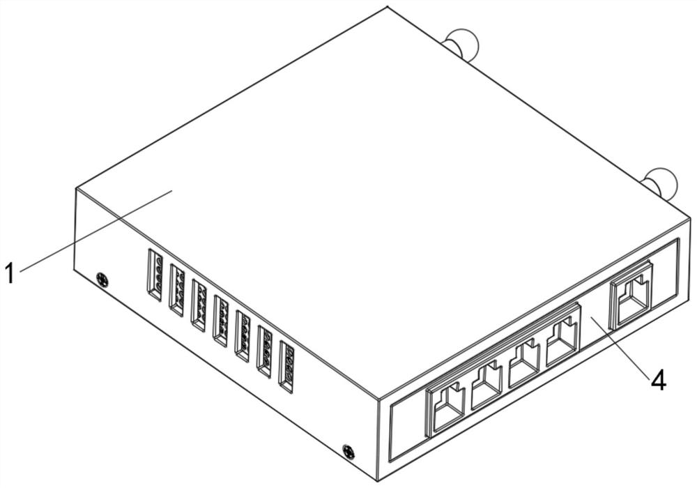
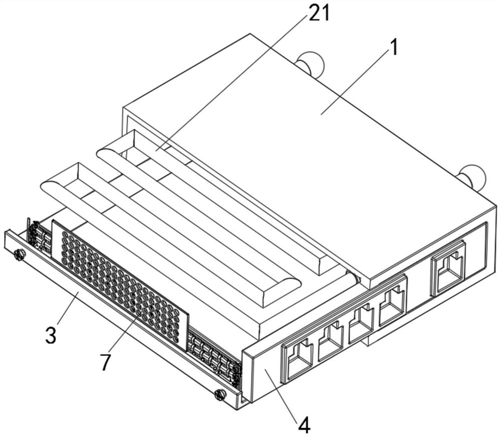
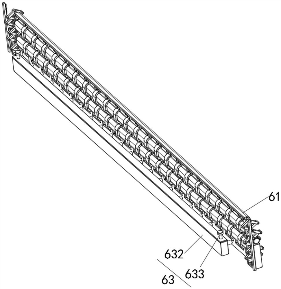
[0038] see Figure 1-Figure 9 , a network switch with anti-electromagnetic interference function, comprising a main casing 1, a heat dissipation device 2 is arranged inside the main casing 1, a bottom plate 3 is fixed on the bottom of the main casing 1 by screws, and the inner side of the main casing 1 is fixed A component board 4 is installed, and a telescopic device 5 and a shielding strengthening device 6 are fixedly connected inside the main casing 1 and on the upper side of the bottom plate 3;

[0039] The heat dissipation device 2 includes a circulation pipe 21, a water pump 22 and a promotion device 23. A circulation pipe 21 is provided on the inner upper side of the main casing 1, a water pump 22 is fixedly installed on the circulation pipe 21, and a promotion device is fixedly connected to the right side of the circulation pipe 21. twenty three.

[0040] Further, the structure of the promotion device 23 includes a branch pipe 231 and a spacer 232 , a branch pipe 231 ...


PUM


Abstract

The invention relates to the technical field of network switches, and discloses a network switch with an anti-electromagnetic interference function, which comprises a main shell, a heat dissipation device is arranged in the main shell, a bottom plate is fixedly mounted at the bottom of the main shell through screws, and the heat dissipation device comprises a circulating pipe, a water pump and a promoting device. And a circulating pipe is arranged on the upper side of the interior of the main shell, a water pump is fixedly installed on the circulating pipe, and a promoting device is fixedly connected to the right side of the circulating pipe. According to the network switch with the anti-electromagnetic interference function, through the cooperation among the water pump, the circulating pipe, the spacer and the branch pipe, the purpose of carrying out water-cooling heat dissipation on the interior of the network switch is achieved, the branch pipe is arranged on the outer side of the main shell, and the head of the branch pipe is in a spherical shape; and when the water flow in the circulating pipe flows into the branch pipe, efficient heat dissipation is carried out, the water-cooling heat dissipation effect is further improved, and therefore the problem that the service life is short is solved.

Description

technical field [0001] The invention relates to the technical field of network switches, in particular to a network switch with anti-electromagnetic interference function. Background technique [0002] The network switch is a device for expanding the network, which can provide more connection ports in the sub-network to connect more computers. It has the characteristics of high cost performance, high flexibility, relative simplicity, and easy implementation. With the continuous development, the development trend of network switches tends to be more and more multi-functional. [0003] The existing network switches mainly have the following technical defects: First, the traditional network switches mainly use the outer casing to block the interference of external electromagnetic waves to the network switch. However, the outer casing is mainly formed by assembling the main casing and the bottom plate, and then the outer casing. There is a gap between the inside of the body and...

Claims


Application Information

Patent Timeline
Patent Type & Authority Applications(China)
IPC IPC(8): H04L49/10H04Q1/02H04Q1/10
CPCH04L49/10H04Q1/10H04Q1/035H04Q1/116
Inventor 不公告发明人
Owner 深圳鼎盛时代科技有限公司
Why Eureka
Try Eureka