Oil separation tank for restaurant sewage

A technology for catering sewage and grease traps, which is applied in the directions of water/sewage multi-stage treatment, water/sludge/sewage treatment, grease/oily substance/floating matter removal device, etc. The oil effect is poor, the filter element is easy to clog and other problems, and the oil removal effect is good, the filtering effect is increased, and the filter element is easy to replace.

Pending Publication Date: 2022-05-27
宁波绿欣环保科技有限公司
View PDF9 Cites 0 Cited by
  • Summary
  • Abstract
  • Description
  • Claims
  • Application Information

AI Technical Summary

Problems solved by technology

[0003] At present, the sewage grease trap on the market adopts a fixed filter element structure. The principle is to divide the grease trap into three pools on the left, middle and right through the partition plate, which are respectively the sedimentation part, the slag removal part, the oil removal part, and the separation part. There are openings on the plate to connect the three pools. The function of the sedimentation part is to settle the heavy solids in the sewage to the bottom of the pool. There is a columnar filter element in the middle of the slag removal part and the oil removal part. When the sewage passes through the filter element, it can be The food residue and grease in the sewage are removed, and finally the sewage is filtered and flows out from the water outlet. There is a piston in the water inlet pipe to scrape off the residue remaining in the pipe. In the middle of the pool, this will cause part of the sewage to flow directly out of the grease trap without being filtered by the filter element, the effect of removing residue and oil is poor, and the filter element is large in size, it is troublesome to replace and clean the filter element, and the filter element is also easy to block

Method used


Image

  • Oil separation tank for restaurant sewage

Examples


Embodiment 1

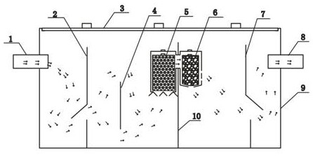
[0015] Please refer to figure 1 , a catering sewage grease trap provided by this embodiment includes a box body 9, and a water inlet pipe 1 and a water outlet pipe 8 are respectively fixed on the left and right sides of the box body 9 near the upper end surface. At the same time, the box body 9 The top surface opening is hollow inside, the top surface of the box body 9 is movably fixed with the box body cover plate 3, and the lower end surface of the box body 9 is fixed with three partition plates arranged horizontally with each other, from left to right are the front partition plate 2, the middle partition The plate 10 and the rear partition 7, the three partitions divide the box 9 into four cavities, from left to right are the sedimentation part, the slag removal part, the oil removal part I and the oil removal part II. Each partition has an opening, the opening of the front partition and the opening of the rear partition are horizontal, the opening of the middle partition i...


PUM


Abstract

The invention relates to an oil separation tank for restaurant sewage. According to the restaurant sewage oil separation tank, a partition plate is additionally arranged in a tank body on the basis of an existing structure, so that a precipitation part, a slag removal part, an oil removal part I and an oil removal part II are sequentially formed in the tank body, meanwhile, each partition plate is provided with an opening, and a baffle opposite to the opening of the partition plate between the precipitation part and the slag removal part is additionally arranged in the slag removal part; the two sides of an opening of a partition plate between the slag removal part and the oil removal part I are each provided with a filter element frame, a rough filtration filter element is movably fixed in the filter element frame of the slag removal part, and a fine filtration filter element is movably fixed in the filter element frame of the oil removal part I; the bottom of the rough filtration filter element frame is open, the bottom and the side face of the fine filtration filter element frame are open, the rough filtration filter element and the fine filtration filter element can be taken out of the respective filter element frames, and the box body is movably sealed and covered by the box body cover plate on the basis of an existing box body, so that the purification effect is better, and meanwhile, the filter elements are convenient to replace.

Description

technical field [0001] The invention belongs to the field of sewage purification, in particular to a grease trap for catering sewage. Background technique [0002] Catering sewage grease trap is a device installed in the sewage system of restaurants, canteens and other dining places. Its main function is to separate and filter the sewage containing food residues and grease after the tableware has been washed, and then discharge it to the sewer. It plays a role in preventing the blockage of the sewage system and ensuring the smooth use of the sewage system. [0003] At present, the sewage grease trap on the market adopts a fixed filter element structure. There are openings on the plate to connect the three pools. The function of the sedimentation part is to settle the heavier solids in the sewage to the bottom of the pool. There is a columnar filter element in the middle of the slag removal part and the oil removal part. When the sewage passes through the filter element, it ...

Claims


Application Information

Patent Timeline
Patent Type & Authority Applications(China)
IPC IPC(8): C02F9/02
CPCC02F9/00C02F1/40C02F2001/007C02F1/001
Inventor 翁雪君
Owner 宁波绿欣环保科技有限公司
Why Eureka
Try Eureka