Bar chart drawing device for economics teaching
A bar chart and economic technology, applied in the direction of preventing slippage, printing, writing utensils, etc., can solve the problems of affecting teaching quality, reducing drawing efficiency, occupying a large space, etc., to improve drawing efficiency, improve Flexibility, Efficiency Improvement
- Summary
- Abstract
- Description
- Claims
- Application Information
AI Technical Summary
Problems solved by technology
Method used
Image
Examples
Embodiment 1
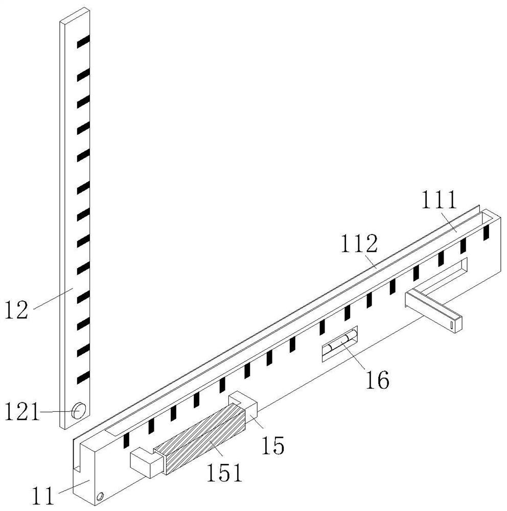
[0034] Embodiment 1, please refer to the attached Figure 1-8 As shown, a bar graph drawing device for economics teaching includes a foldable drawing assembly 1, and the foldable drawing assembly 1 includes a horizontal ruler body 11, a vertical ruler body 12, an auxiliary vertical ruler 13 and an auxiliary horizontal ruler 14. The horizontal ruler body 11 is provided with a first receiving groove 111 and a second receiving groove 112, as well as several hemispherical positioning grooves 113 linearly distributed at equal intervals on both sides of the inner wall of the first receiving groove 111. The lower end of the vertical ruler body 12 is provided with There is a first damping shaft 121, and both ends of the first damping shaft 121 are rotatably connected to the inner wall of the second receiving slot 112. The lower end of the auxiliary vertical ruler 13 is provided with a fixed-point limiting component 2, and the upper end of the inner cavity of the auxiliary vertical rule...
Embodiment 2
[0035] In the second embodiment, please refer to the attached figure 1 and 3 As shown, a magnetic strip 19 is embedded in the groove on the other side of the outer wall of the horizontal ruler body 11, and the horizontal ruler body 11 is adsorbed on the blackboard through the magnetic stripe 19, which is convenient for users to compare drawings. An elastic lanyard 4 is arranged at a top corner of the lower surface of the outer wall of the ruler body 11 , and the whole device can be hung up when not in use through the elastic lanyard 4 .
Embodiment 3
[0036] Embodiment 3, please refer to the attached Figure 5 and 6As shown, moving chute 131 is respectively provided on both sides of the inner wall of the auxiliary vertical ruler 13, and each of the moving chute 131 is slidably connected with the moving slider 32, and a plurality of the rectangular positioning holes 34 are linearly arranged at equal intervals. On the side wall of the auxiliary vertical ruler 13, through the mutual cooperation between the moving sliding block 32 and the moving chute 131, the auxiliary horizontal ruler 14 can slide up and down stably on the auxiliary vertical ruler 13, which is convenient for better alignment of the bar shape. The height of the figure is drawn and measured. The bottom of the outer wall of the moving groove block 21 is provided with a T-shaped pull handle 25, and is in a sliding connection with the first receiving groove 111. The block 21 is pulled to move linearly in the first receiving groove 111 , and the engaging force bet...
PUM
 Abstract
Description
Claims
Application Information
 - R&D
- Intellectual Property
- Life Sciences
- Materials
- Tech Scout
- Unparalleled Data Quality
- Higher Quality Content
- 60% Fewer Hallucinations
Browse by: Latest US Patents, China's latest patents, Technical Efficacy Thesaurus, Application Domain, Technology Topic, Popular Technical Reports.
© 2025 PatSnap. All rights reserved.Legal|Privacy policy|Modern Slavery Act Transparency Statement|Sitemap|About US| Contact US: help@patsnap.com


